Radar array antenna

Active Publication Date: 2015-02-26
ACE ANTENNA
View PDF0 Cites 7 Cited by
  • Summary
  • Abstract
  • Description
  • Claims
  • Application Information

AI Technical Summary

Benefits of technology

[0015]An aspect of the invention proposes a radar array antenna using

Problems solved by technology

However, in the conventional radar array antenna, the branch line 102 is joined to a middle

Method used


Image

  • Radar array antenna
  • Radar array antenna
  • Radar array antenna

Examples


Embodiment Construction

of the present invention relate to a radar array antenna.

[0003]2. Description of the Related Art

[0004]A radar is a device that detects the distance and direction of a remote object or target and information on the surroundings of the target by sending beam signals to the target to receive and analyze the reflected waves.

[0005]A radar utilizes the linear directionality and reflective characteristics of radio waves, enabling detection unaffected by darkness, rain, snow, and other circumstances that may reduce visibility, and in recent times, radar devices are also being used in automotive vehicles for gathering various information.

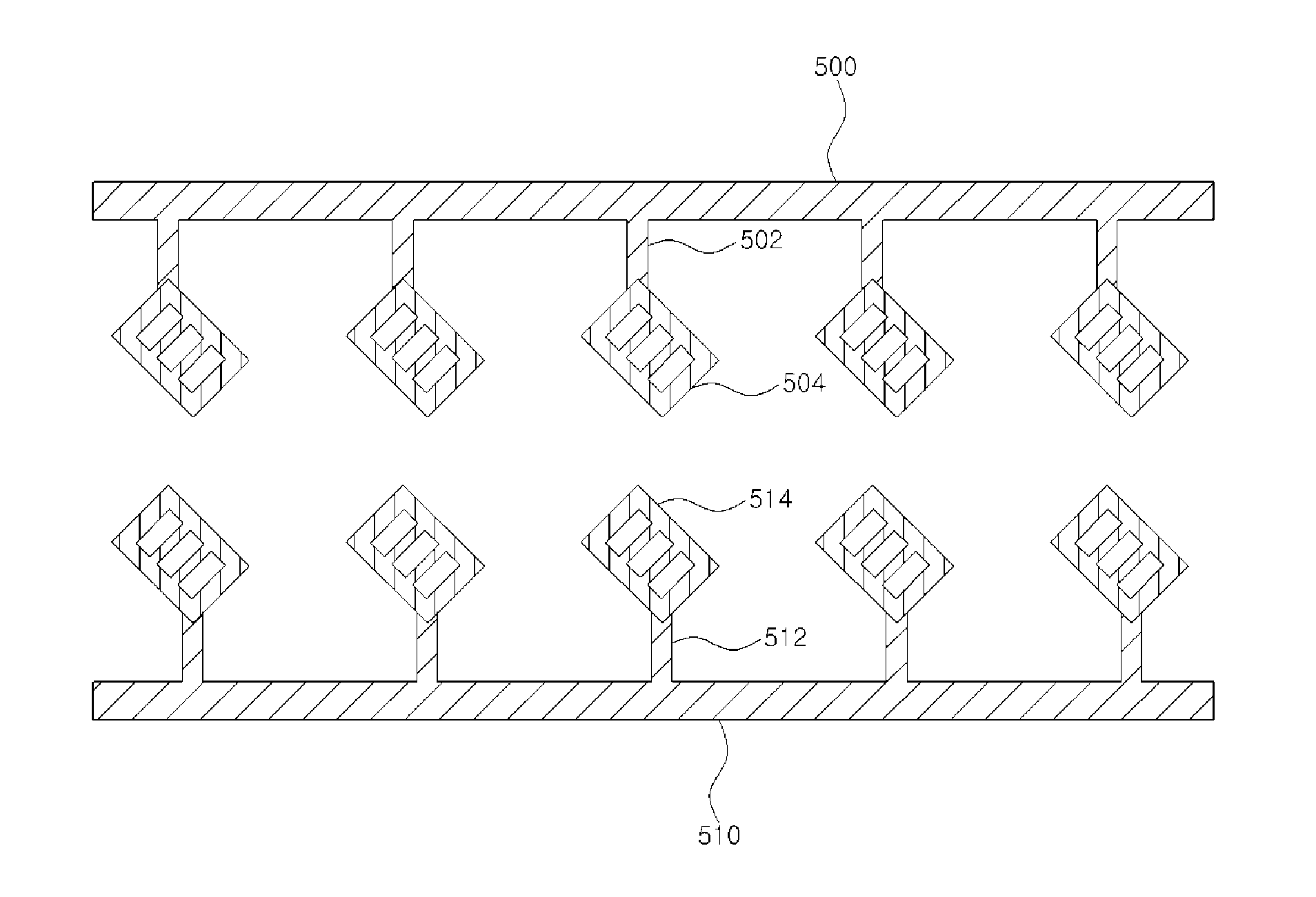
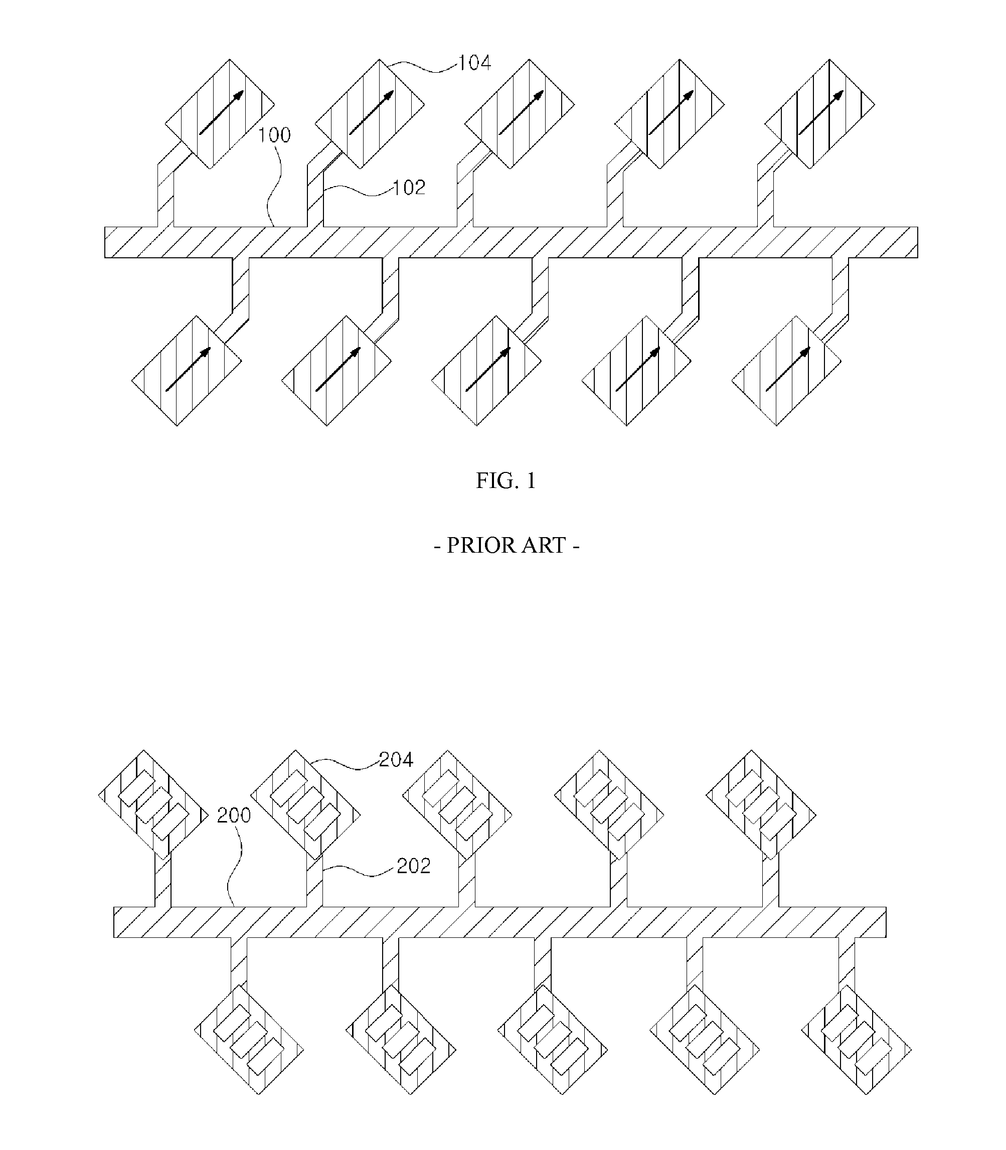
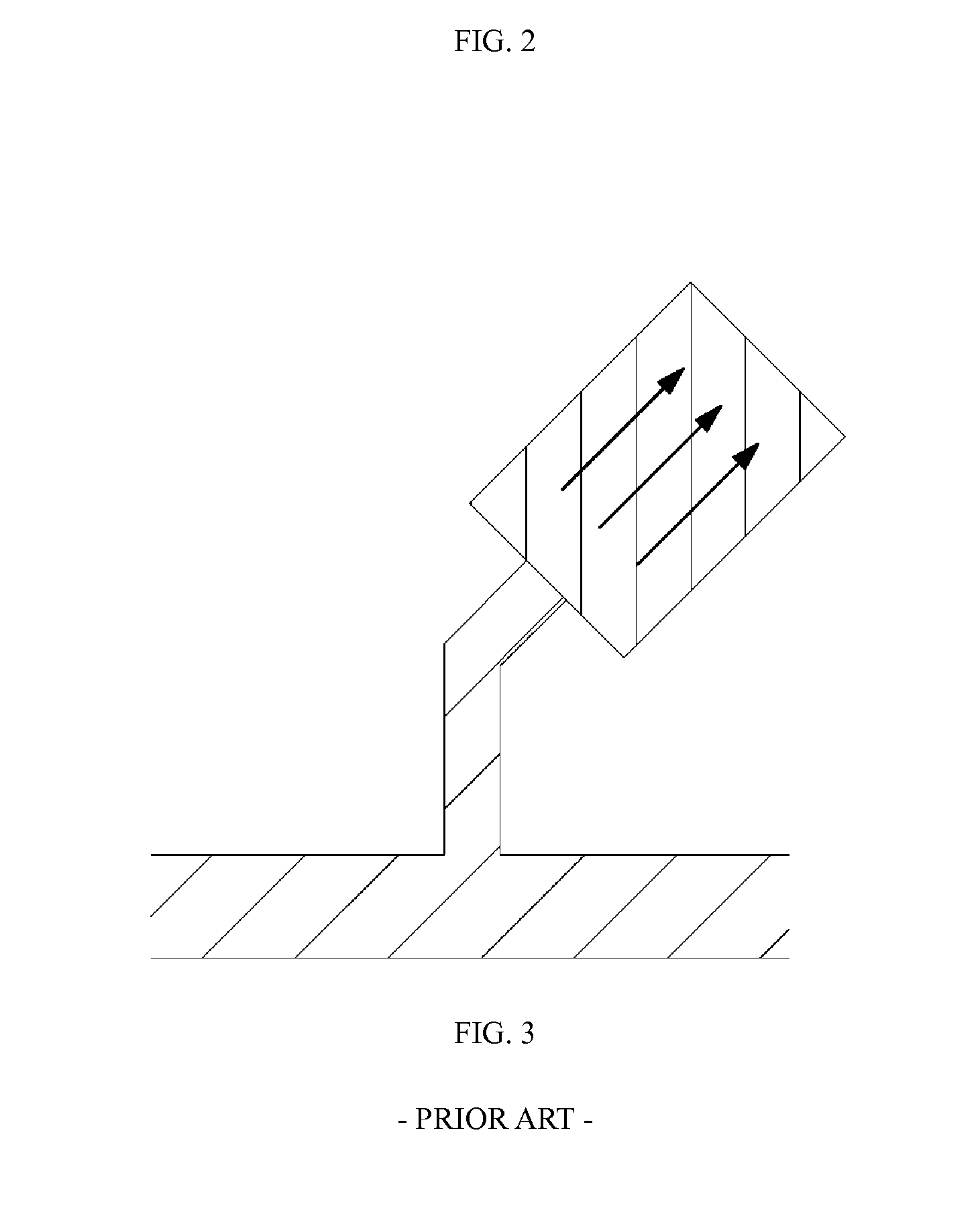
[0006]While various types of antennas may be used for a radar antenna, one type of antenna commonly used is the array antenna having a microstrip patch.

[0007]The array antenna using a microstrip patch may include a main feed line and several branch lines that branch out from the main feed line, with a microstrip patch joined to each of the multiple branch li...


PUM


Abstract

Disclosed is a radar array antenna. The radar array antenna includes: at least one main power feed line electrically coupled to a feed point; a plurality of branch lines branched from the main feed line; and a plurality of patch radiators, each having a square shape, and respectively coupled to the plurality of branch lines. Each of the plurality of branch lines is coupled to one edge of each of the patch radiators. According to the disclosed radar array antenna, the power feed line of the radar array antenna may be minimized in size by using the patch radiator to reduce power losses and realize miniaturization.

Description

CROSS-REFERENCE TO RELATED APPLICATIONS[0001]This application is a National Phase Application of PCT International Application No. PCT / KR2013 / 001044, which was filed on Feb. 8, 2013, and which claims priority from Korean Patent Application No. 10-2012-0013408 filed with the Korean Intellectual Property Office on Feb. 9, 2012. The disclosures of the above patent applications are incorporated herein by reference in their entirety.BACKGROUND[0002]1. Technical Field Embodiments of the present invention relate to a radar array antenna.[0003]2. Description of the Related Art[0004]A radar is a device that detects the distance and direction of a remote object or target and information on the surroundings of the target by sending beam signals to the target to receive and analyze the reflected waves.[0005]A radar utilizes the linear directionality and reflective characteristics of radio waves, enabling detection unaffected by darkness, rain, snow, and other circumstances that may reduce visib...

Claims


Application Information

Patent Timeline
IPC IPC(8): H01Q21/29H01Q21/00
CPCH01Q21/0075H01Q21/293H01Q1/3233H01Q21/065H01Q21/08H01Q1/46H01Q13/08
Inventor MILYAKH, YAROSLAVKIM, HAK-KYOUNSUN, DA YOUNG
Owner ACE ANTENNA
Why Eureka
Try Eureka