Finned jacket with core wrap for use in LAN cables

Inactive Publication Date: 2009-09-24
COMMSCOPE INC
View PDF10 Cites 7 Cited by
  • Summary
  • Abstract
  • Description
  • Claims
  • Application Information

AI Technical Summary

Benefits of technology

[0007]First, there is a general goal in the design to maximize the air channel size and minimize the fin size. The reason for the general goal is to include as much air as possible in the immediate vicinity of the cable core (twisted wire pairs—possibly with a tape or star separator) and to include as little jacket material (e.g., fins) in the immediate vicinity of the cable core. Air has a dielectric

Problems solved by technology

One drawback appreciated by the Applicant is that in the quest to expand the channel width, the possibility of a

Method used


Image

  • Finned jacket with core wrap for use in LAN cables
  • Finned jacket with core wrap for use in LAN cables
  • Finned jacket with core wrap for use in LAN cables

Examples


Example

[0043]The cable 51A of the first embodiment of the invention has eight projections 55 forming eight air channels 13. The cable 51A of the first embodiment has no separator 85A or 85B. The cable 51B of the second embodiment of the invention has a jacket 57A with six projections 55 forming six air channels 13. The cable 51B of the second embodiment has a generally flat tape separator 85B.

[0044]The cables 51A and 51B of the first and second embodiments both include an identical core wrap 30. The core wrap 30 at least partially surrounds the cable core. In the depicted first and second embodiments, the core wrap 30 is formed by a sheet of material with a length as long as the cable 51A or 51B, a width which is slightly larger than a circumference of the cable core (to permit an overlap), such that the core wrap 30 completely surrounds the cable core along a length of the cable 51A or 51B. Hence, the core wrap 30 abuts the plurality of projections 55 of the jacket 57 and 57A. The wires o...

Example

[0047]FIG. 7 is a perspective view of a cable 51C in accordance with a third embodiment of the present invention. The cable 51C of the third embodiment of the invention has the jacket 57A with six projections 55 forming six air channels 13. The cable 51B of the third embodiment has the plus-shaped separator 85A.

[0048]The cable 51C of the third embodiment includes a core wrap 30A which only partially surrounds the cable core, leaving an air gap 32 along the length of the cable 51C. The core wrap 30A is formed by a tape traveling around the cable core in an open helix shape. In the depicted embodiment, the tape would have a length much greater than a length of the cable 51C and a width which is about 0.2 inches. The core wrap 30A is helically wrapped about the cable core at an angle of about thirty degrees, which creates a helical air gap 32 of about 0.4 inches along the length of the cable 51B. Of course, different tape widths and angles of helical winding may be employed so as to ch...

Example

[0050]FIG. 8 is a perspective view of a cable 51D in accordance with a fourth embodiment of the present invention. FIG. 9 is a cross sectional view taken along line IX-IX in FIG. 8. The cable 51D of the fourth embodiment of the invention has a jacket 57B with twelve projections 55 forming twelve air channels 13. The cable 51D of the fourth embodiment has the plus-shaped separator 85A.

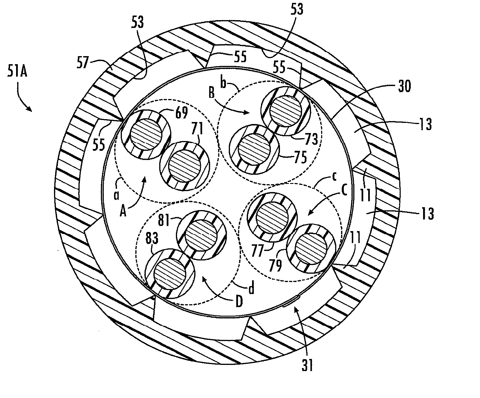
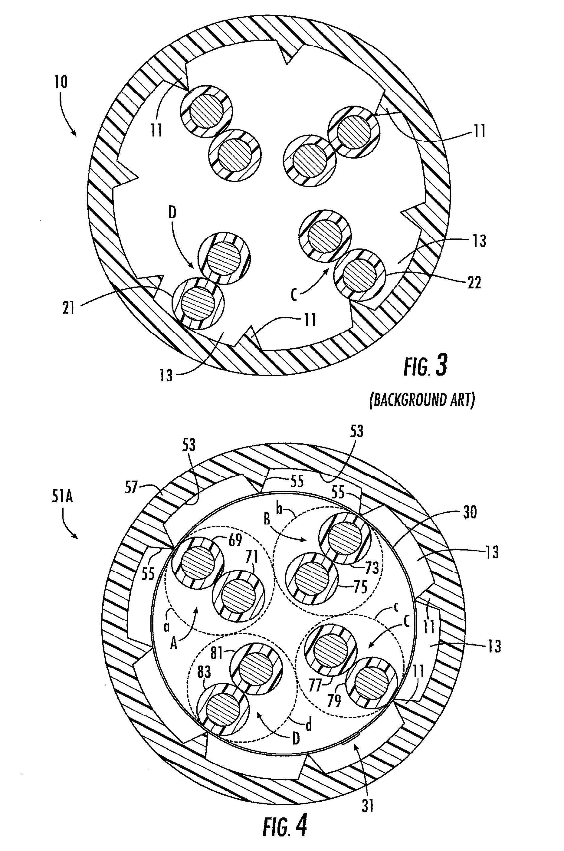
[0051]The cable 51D of the fourth embodiment includes a core wrap 30B which completely surrounds the cable core along the length of the cable 51D. The core wrap 30B is formed by a tape traveling around the cable core in an overlapping helix shape. In the depicted embodiment, the tape would have a length much greater than a length of the cable 51D and a width which is about 0.2 inches. The core wrap 30B is helically wrapped about the cable core at an angle of about 5 to 10 degrees, which creates a continuous helically-shaped, small overlapped area 31 with the previous helical wrap. Of course, different t...


PUM


Abstract

A twisted pair cable includes a jacket having a plurality of projections extending away from an inner surface of the jacket to define a plurality of air channels along the inner surface of the jacket. A cable core, including four twisted wire pairs and possibly a separator, resides within the jacket. A core wrap at least partially surrounds the cable core, such that the core wrap abuts the projections and prevents any wire of the cable core from entering into one of the air channels. In a preferred embodiment, the core wrap is formed by a tape in a helix shape about the cable core, wherein the tape partially overlaps itself in forming the helix shape, the tape includes an adhesive layer, and the overlapped portions of the tape are attached to each other via the adhesive to form an airtight connection.

Description

[0001]This application claims the benefit of U.S. Provisional Application No. 61 / 037,900, filed Mar. 19, 2008, the entire contents of which are herein incorporated by reference.BACKGROUND OF THE INVENTION[0002]1. Field of the Invention[0003]The present invention relates to communication cables. More particularly, the present invention relates to a twisted pair cable having a jacket with projections on an inner wall to provide air channels around a core of the twisted wire pairs, and to a structure to permit maximization of the air channel dimensions.[0004]2. Description of the Related Art[0005]Jackets with projections or fins on an inner wall of the jacket are known in the prior art. For example, U.S. Pat. No. 3,894,172, U.S. Pat. No. 5,796,046, U.S. Pat. No. 7,238,886, and U.S. publication 2005 / 0133246, each of which is herein incorporated by reference, show a cable having internal fins or projections.SUMMARY OF THE INVENTION[0006]The applicant has appreciated one or more drawbacks...

Claims


Application Information

Patent Timeline
IPC IPC(8): H01B11/02
CPCH01B11/04H01B7/184
Inventor WESSELS, JR., ROBERT
Owner COMMSCOPE INC
Why Eureka
Try Eureka