Swivel type working vehicle

a working vehicle and swivel technology, applied in mechanical machines/dredgers, transportation and packaging, waste collection, etc., can solve the problems of serious lowering of the working efficiency of the swivel type working vehicle and unsatisfactory rigidity of the boom, and achieve the effect of increasing rigidity

Inactive Publication Date: 2005-03-29
KUBOTA LTD
View PDF14 Cites 25 Cited by
  • Summary
  • Abstract
  • Description
  • Claims
  • Application Information

AI Technical Summary

Benefits of technology

The object of this invention is to provide a swivel type working vehicle having a boom of box-shaped sectional profile with a substantially entire rear region thereof closed by a rear wall to have increased rigidity, and hydraulic pipes received in an internal space of the boom through an opening formed in a proximal end region of the rear wall whereby the boom may be actuated during operation without taking care to keep the hydraulic pipes out of contact with other objects.

Problems solved by technology

This has been a cause of seriously lowering the working efficiency of the swivel type working vehicle.
In this construction, though hydraulic pipes for each cylinder are mounted inside the boom, the rigidity of the boom is not satisfactory since part of the boom has a sectional profile opening rearward (i.e. channel-shaped sectional profile) to receive at least part of the boom cylinder in the internal space of the boom.

Method used


Image

  • Swivel type working vehicle
  • Swivel type working vehicle
  • Swivel type working vehicle

Examples


Embodiment Construction

An embodiment of this invention will be described hereinafter with reference to the drawings.

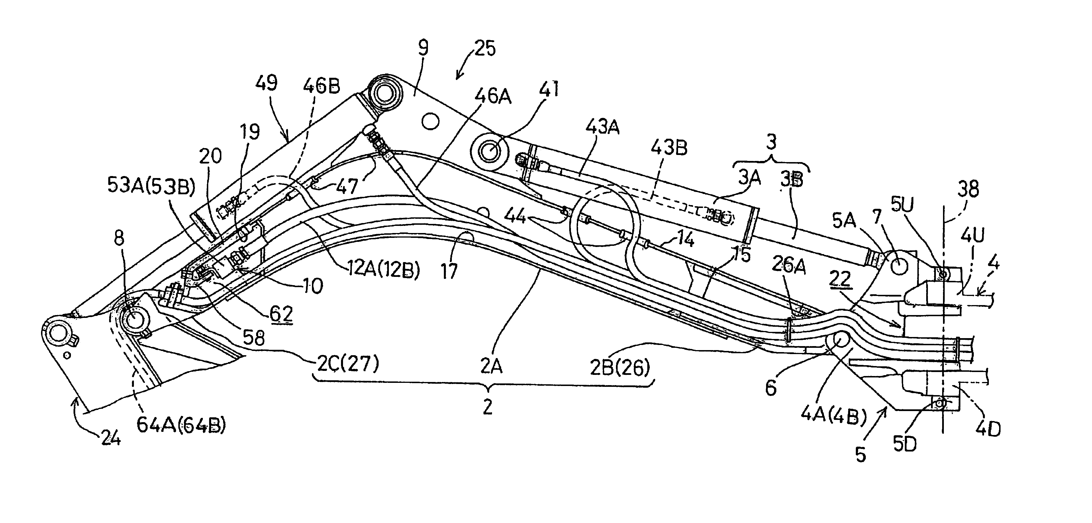
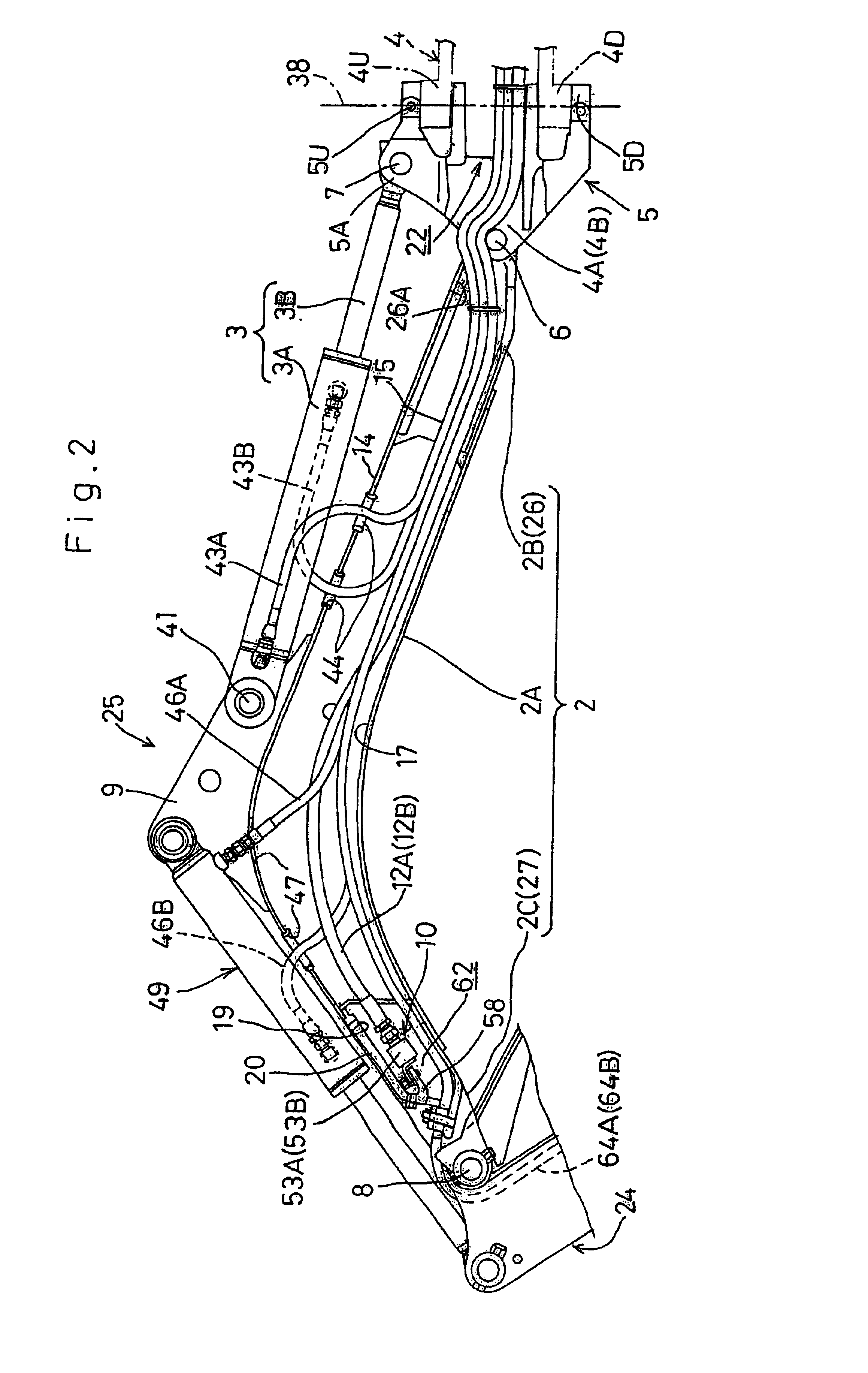
FIGS. 1 through 5 show a swivel type working vehicle, and particularly a hydraulic piping layout thereof, according to this invention.

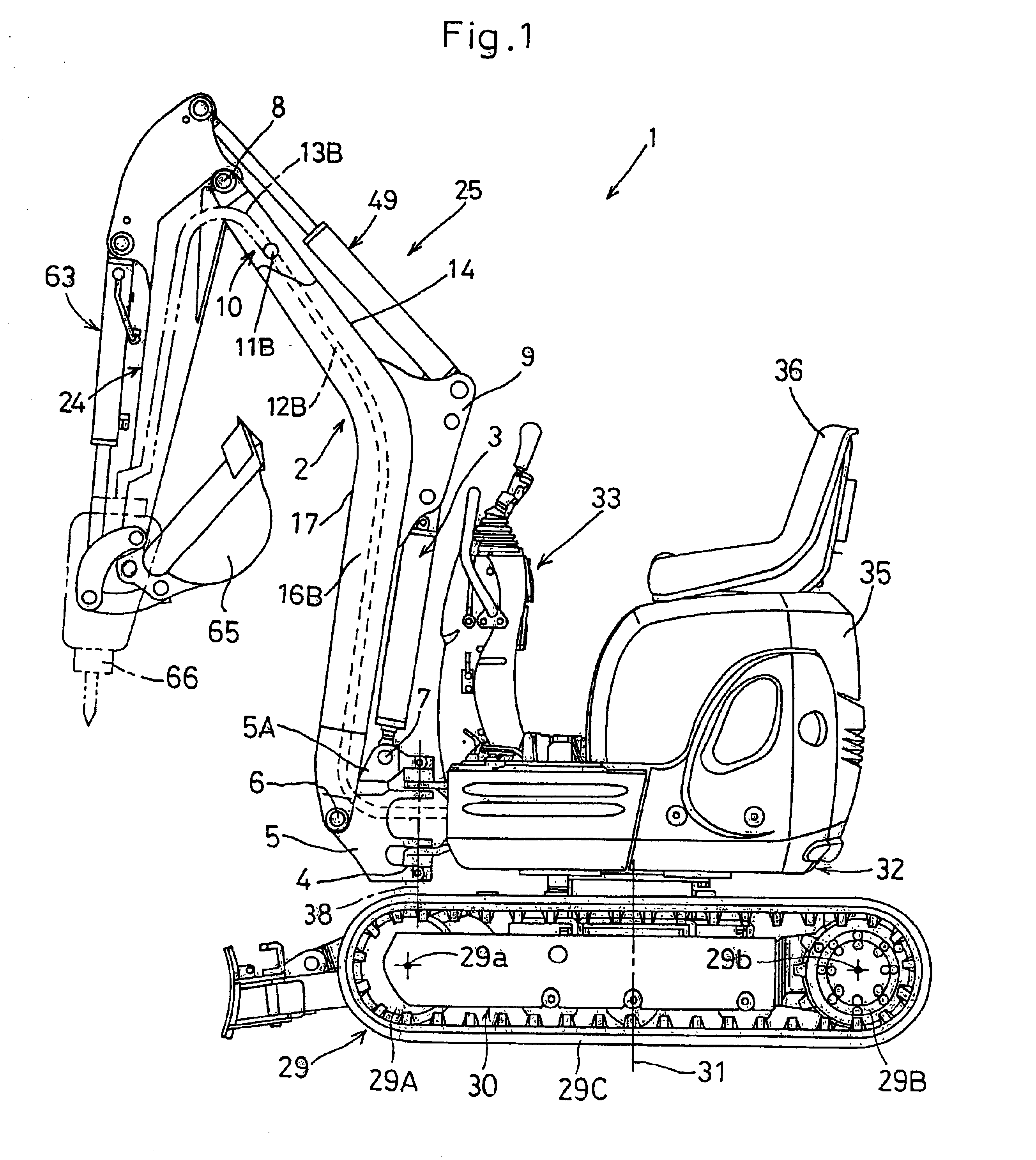
FIG. 1 shows a backhoe exemplifying a swivel type working vehicle 1. The working vehicle 1 has right and left crawlers 29 constituting a running device 30 supporting a swivel base 32 to be swivelable about a vertical swivel axis 31. The swivel base 32 has an excavating assembly 25 disposed at the front thereof and including a boom 2.

Each crawler 29 includes a front roller 29A rotatable about an axis 29a, a rear roller 29B rotatable about an axis 29b, and a crawler belt 29C wound around these rollers.

The swivel base 32 has an engine, a fuel tank and an oil tank (not shown) mounted on a rear portion thereof and enclosed in a cover 35. A driver's seat 36 is disposed above the cover 35. A control box 33 is disposed on a front portion of the swivel base 32 forwardl...


PUM


Abstract

A swivel type working vehicle includes a running device (30), a swivel base (32) mounted on the running device to be swivelable about a vertical swivel axis (31), a swing bracket (5) supported to be swingable about a vertical axis by a flange unit (4) disposed at a front end of the swivel base, a boom (2) having a proximal end (2B) thereof attached to the swing bracket to be swingable about a horizontal axis (6), a boom cylinder (3) having one end thereof connected to the swing bracket and the other end to the boom for swinging the boom, a hydraulic pressure takeoff device (10) disposed in a distal end region (2C) of the boom, and hydraulic pressure takeoff pipes (12A, 12B) for supplying hydraulic pressure to the hydraulic pressure takeoff device (10). The boom (2) is a hollow box having a front wall (17), a left wall (16A), a right wall (16B) and a rear wall (14) extending longitudinally of the boom. The boom cylinder (3) is disposed outside the boom to extend along the rear wall of the boom. The hydraulic pressure takeoff pipes (12A, 12B) extend from the swivel base through a proximal opening (15) formed adjacent the proximal end (2B) into the boom to reach the hydraulic pressure takeoff device.

Description

BACKGROUND OF THE INVENTION1. Field of the InventionThis invention relates to a swivel type working vehicle, such as a backhoe, having a swivel base mounted on a running device to be swivelable about a vertical swivel axis, a swing bracket pivotally supported to be swingable about a vertical axis by a flange unit disposed at the front end of the swivel base, a boom attached at a proximal end thereof to the swing bracket to be swingable about a horizontal axis, a boom cylinder connected at one end thereof to the swing bracket and at the other end to the boom for swinging the boom, a hydraulic pressure takeoff device disposed at a distal end of the boom, and hydraulic pipes for supplying hydraulic pressure to the hydraulic pressure takeout device.2. Description of the Related ArtA swivel type working vehicle such as a backhoe may optionally be equipped with an auxiliary working implement such as a breaker or auger in place of a main working implement such as a bucket. A hydraulic pres...

Claims


Application Information

Patent Timeline
Patent Type & Authority Patents(United States)
IPC IPC(8): E02F3/36E02F3/38E02F9/22E02F3/34E02F3/28E02F3/32E02F9/00
CPCE02F3/325E02F3/38E02F9/2275E02F3/384Y10S414/131E02F9/00
Inventor YUKAWA, KATSUHIKOFUJIWARA, JUNICHI
Owner KUBOTA LTD
Why Eureka
Try Eureka