Auto calibration and personalization of eye tracking system using larger field of view imager with higher resolution

a technology of eye tracking system and imager, which is applied in the field of eye tracking system with a larger field of view and a higher resolution imager, can solve the problems of driver inattention, many fatalities and non-fatal accidents, and high cost, and achieve the effect of adequate resolution

Inactive Publication Date: 2005-03-29
APTIV TECH LTD
View PDF17 Cites 47 Cited by
  • Summary
  • Abstract
  • Description
  • Claims
  • Application Information

AI Technical Summary

Problems solved by technology

Driver inattention may result from drowsiness, use of a telephone, use of a computer, changing stations on a radio, conversing with another occupant of the vehicle, and similar causes.
Whatever the cause, such driver inattention may result in fatalities and non-fatal accidents.
Although there are a number of eye tracking methods, many are quite expensive and many involve undesirable intrusiveness, both undesirable features for a vehicular system.
A disadvantage is that the contrast is lower.
Because the IR illumination has to travel through seven interfaces, the method is very inefficient and requires a relatively powerful illumination source.
This method is simple, but not reliable, due to signal variations over time, and not precise, due to noise levels.
This is a very accurate method, but also quite intrusive.
As noted above, the foregoing methods are unsuitable for vehicular use because of cost and / or intrusiveness, although some produce fairly accurate results.
This requires a complex and expensive auto focus and tracking system.
One problem is that such current eye tracking systems use a small field of view lens to cover a small area around the eye of the driver and an image sensor having a sub-QVGA (“quarter video graphic array) resolution (or one-quarter of the standard 640×480 VGA pixelation).
Because of these limitations, conventional eye tracking systems permit only limited head movement.
If the limited degree of head movement is exceeded by sudden head movement, head rotation, or vibration, for example if the vehicle runs on a rocky road, the system will “lose” the eye and becomes ineffective until the eye can again be tracked which can take some time.
Another problem with such current eye tracking systems is that, since each person has a slightly different ocular profile that can result in a large error in calculation, the eye tracking system needs to be calibrated for each different driver.
In addition to the fairly tedious start-up procedure, periodic recalibration is required because of drift.
In addition to the above problems, the use of electromechanical components inherently renders a system complex and relatively costly and introduces additional areas in which alignment is critical and in which the wearing of mechanical linkages eventually introduces additional errors into the eye tracking system.

Method used


Image

  • Auto calibration and personalization of eye tracking system using larger field of view imager with higher resolution
  • Auto calibration and personalization of eye tracking system using larger field of view imager with higher resolution
  • Auto calibration and personalization of eye tracking system using larger field of view imager with higher resolution

Examples


Embodiment Construction

Reference should now be made to the drawing figures on which similar or identical elements are given consistent identifying numerals throughout the various figures thereof, and on which parenthetical references to figure numbers direct the reader to the view(s) on which the element(s) being described is (are) best seen, although the element(s) may be seen on other figures also.

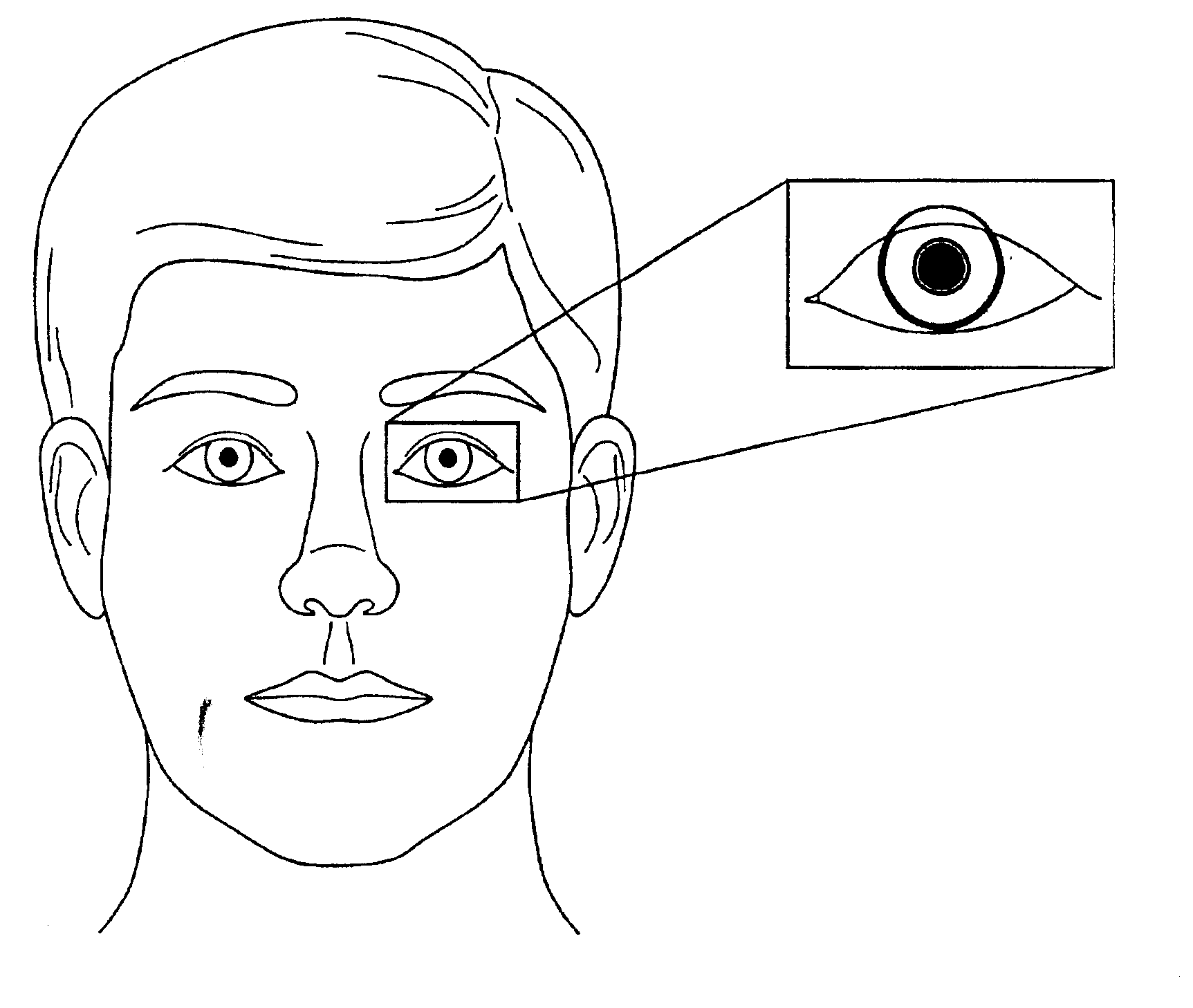
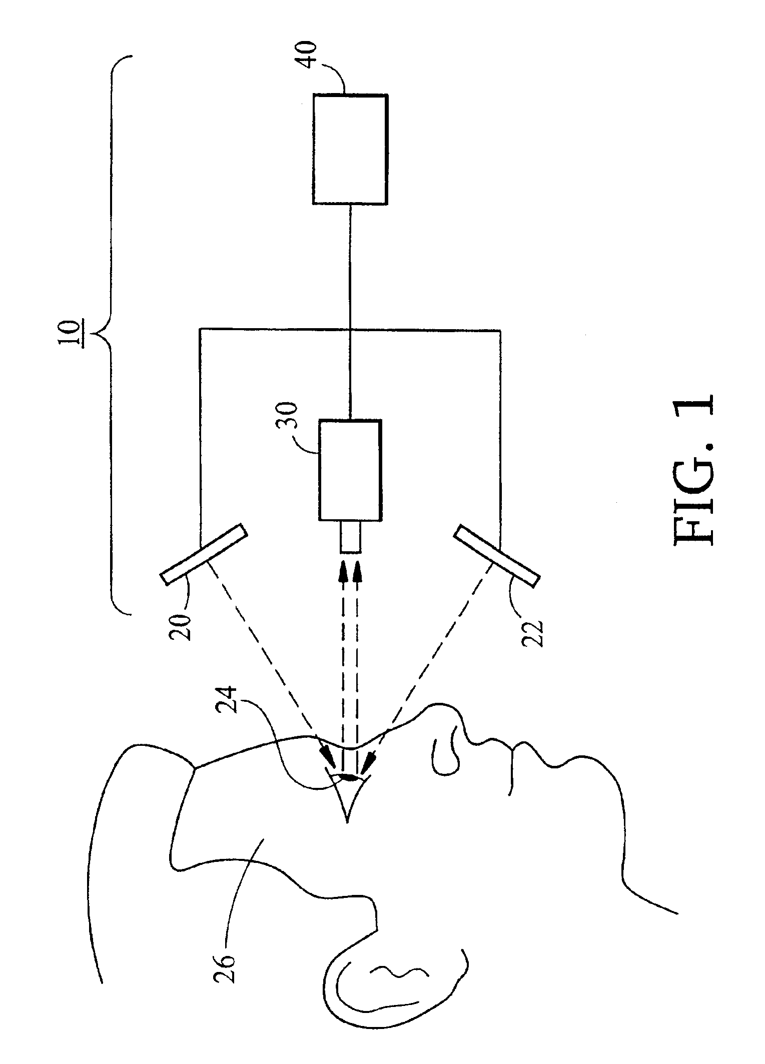
FIG. 1 illustrates an example of a system, according to the present invention, and generally indicated by the reference numeral 10. System 10 includes first and second IR sources 20 and 22 disposed so as to illuminate at least the area around one eye 24 in the face 26 of a user (only the face shown). System 10 also includes a sensor module 30 disposed so as to receive reflections from the eye and to track movements of eye 24. Sensor module 30 could include electronic pan tilt to compensate for head and eye movement and the sensor module provides input to processing and control circuitry in a processing platfor...


PUM


Abstract

In preferred embodiments, apparatus for and method of eye tracking, including, in sequence, the steps of: viewing an entire face of a person to obtain predetermined facial features of the person to identify or not the said person; if the person is identified, retrieving a previously stored ocular profile of the person based on said predetermined facial features; using said ocular profile to track movement of an eye of said person. If the person is not identified, an ocular profile is created.

Description

BACKGROUND OF THE INVENTION1. Field of the InventionThe present invention relates to eye tracking systems generally and, more particularly, but not by way of limitation, to novel eye tracking system with a larger field of view and a higher resolution imager.2. Background ArtWhile the present invention is described generally in the context of determining inattentiveness of the driver of a vehicle, it will be understood that the invention is application, as well, to any situation in which tracking of eye movements is desirable.Communities in which eye tracking is used include the medical, research, and academic communities where eye tracking is useful, for example, in determining psychological response and how a person scans.A large number of the approximately 35,000 vehicular deaths and a much larger number of vehicular accidents each year in the United States can be attributed to driver inattention. Driver inattention may result from drowsiness, use of a telephone, use of a computer...

Claims


Application Information

Patent Timeline
Patent Type & Authority Patents(United States)
IPC IPC(8): A61B3/113A61B5/117G06K9/00G07C9/00G08B21/00G06K9/68G08B21/06
CPCA61B3/113A61B5/117G06K9/00221G08B21/06G06K9/6814G07C9/00158G06K9/00604G07C9/37G06V40/16G06V40/19G06V30/244
Inventor WITT, GERALD J.SCHARENBROCH, GREGORY K.LI, JIANHUA
Owner APTIV TECH LTD
Why Eureka
Try Eureka