Automatic closing door hinge, automatic closing door mechanism, and hinge of automatic closing door mechanism

a technology of automatic closing door and hinge, which is applied in the direction of wing opener, multi-purpose tools, constructions, etc., can solve the problems of unsatisfactory products to be accepted by customers, unfavorable product acceptance, and foregoing automatic closing door mechanism is not smooth in opening or closing the door, etc., to achieve easy manufacturing, reduce weight, and simple structure

Inactive Publication Date: 2005-08-16
SAWA MASAKO +1
View PDF20 Cites 35 Cited by
  • Summary
  • Abstract
  • Description
  • Claims
  • Application Information

AI Technical Summary

Benefits of technology

[0010]The present invention has been made in order to solve the foregoing problem. It is an object thereof to provide an automatic closing door hinge, an automatic closing door mechanism, and a hinge of the automatic closing door mechanism simple in structure, which can be manufactured easily at low cost and reduced in size and weight and saved in space, and further smoothly opening the door and closing the door with damped, for example, while making use of a merit of an automatic closing door mechanism utilizing the action of air cushioning freely from staining the surrounding due to oil leak or so.
[0050]Meanwhile, in the invention, in the case of a structure to engage between the cam groove formed in the outer periphery of the operation rod and the penetration hole formed in the piston or sphere arranged in the recess, working or manufacture is easy as compared to the case of forming a female thread on the piston, e.g. it is satisfactory to work a piston part by making a cylinder and opening a hole therein. Also, because it is the sphere that is to move engaging with the cam groove, cam groove slant or pitch can be freely set. Furthermore, the sphere movement along the cam groove is smooth with less frictional resistance, enabling the piston to advance and retract smoothly.

Problems solved by technology

However, the foregoing automatic closing door mechanism is not smooth in opening the door or in closing the door while damping, i.e. unsatisfactory as a product to be actually accepted by the customer.

Method used


Image

  • Automatic closing door hinge, automatic closing door mechanism, and hinge of automatic closing door mechanism
  • Automatic closing door hinge, automatic closing door mechanism, and hinge of automatic closing door mechanism
  • Automatic closing door hinge, automatic closing door mechanism, and hinge of automatic closing door mechanism

Examples


first embodiment

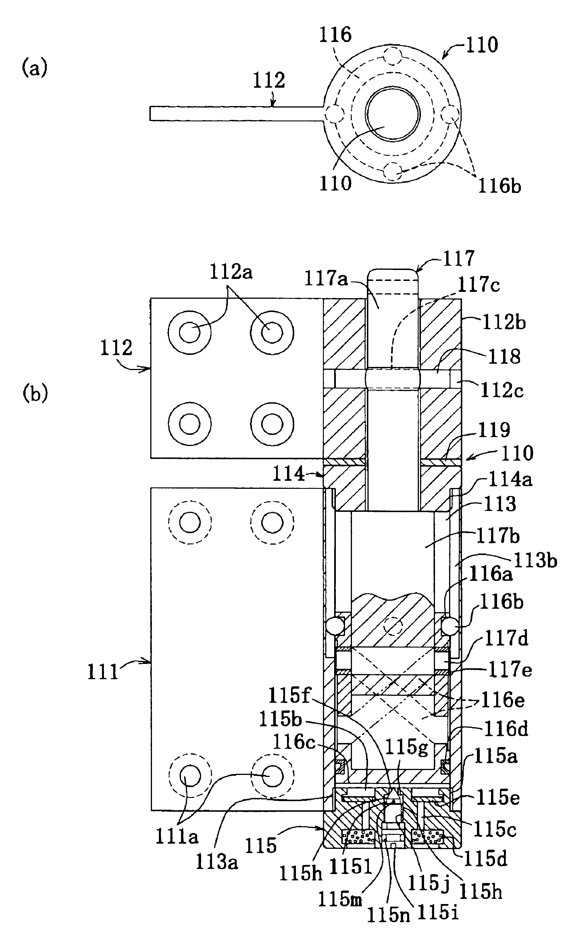
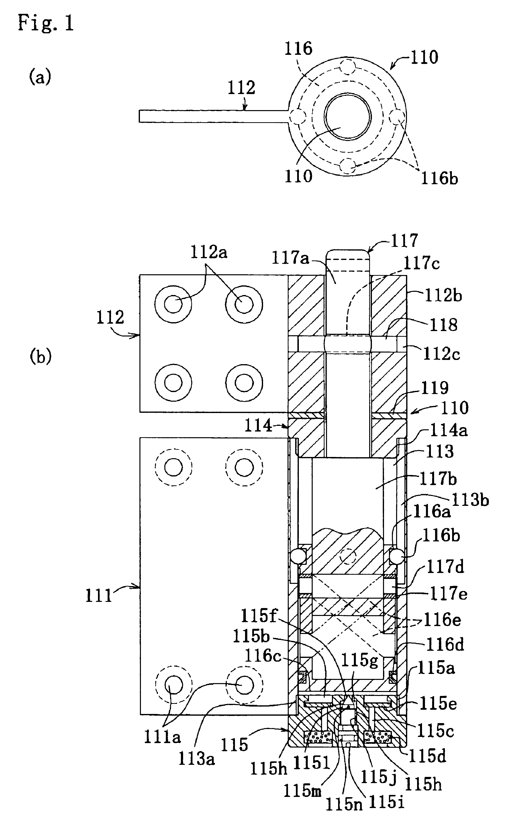
[0084]In the first example hinge 110 of the first embodiment, a compression coiled spring may be accommodated between the piston 116 top surface and the cap 114 underside within the cylinder 113. The compression coiled spring is to be compressed by an ascend of the piston 116 during opening the door, whose restoration force acts to force the piston 116 down. In association with a return motion of the piston 116, the other wing plate 112 rotates in a direction toward closing the door. Incidentally, the compression coiled spring may be appropriately provided in position or the like, provided that the other wing plate 112 is structured to rotate in a direction toward closing the door.

[0085]In the case of using the first example hinge 110 of the first embodiment, another hinge can be suitably used to rotate the other wing plate 112 in a direction toward closing the door. The other hinge has a piston received in a cylinder having a circular cylindrical form provided, for example, on one ...

second embodiment

[0115]In using the first example hinge 21 of the second embodiment, two hinges 21, 21 for example are used as one set, to attach one wing plate 22 of the hinge 21 on a doorframe while the other wing plate 23 on a door, thereby structuring an automatic closing door mechanism. In the attached hinge 21 in a door closed state, the sphere 274 is at the lowest end in the cam groove 29 within the cylinder 24. The piston 27 is in a position that its underside is close to the top surface of the cap 26. Incidentally, the hinges 21 used on the automatic door closing mechanism are in a suitable number.

[0116]In case the door is opened, the other wing plate 23 fixed on the door and the operation rod 28 are rotated by a door opening action. By rotating the cam groove 29, the sphere 274 moves up along the slant region 291 of the cam groove 29. The piston 27 ascends while compressing the compression coiled spring 210. On this occasion, the sphere 275 rolls along the recess groove 241, to smoothen to...

third embodiment

[0170]In the second example hinge 31b of the third embodiment in a state the door is closed, the piston 35 is in a lowermost position. In response to the action to open the door, by circumferentially rotating the other wing plate 33, the operation rod 34 and the male thread 341 thereof, the piston 35 ascends associatively with the rotation. The piston 35, because rolled along the recess groove 3221 while the sphere 352 is being held by the recess groove 3221, ascends without rotation within the cylinder 322. As the piston 35 ascends, the pressure is reduced at between the cap 36 and interior part 37 and the piston 35 within the cylinder 322. Due to pressure reduction, the valve plate 375 floats up (see FIG. 16), so that air is allowed to flow at the air flow-in port 373 to between the cap 36 and interior part 37 and the piston 35 within the cylinder 322, thus increasing or forming an air collection.

[0171]In case automatic door closing operation is effected by the separate hinge, e.g...


PUM


Abstract

An automatic closing door hinge, an automatic closing door mechanism, and a hinge of the automatic closing door mechanism, for smoothly opening a door or closing, with damping, a door. For example, an automatic door closing mechanism has a hinge having a pair of wing plates one of which has a cylinder in a circular cylindrical form received therein a piston, the other wing plate fixing an upper portion of an operation rod engaged with the piston, the piston being to be advanced and retracted through the operation rod associatively with a rotation of the other wing plate. The automatic closing door mechanism comprises a cam formed on the piston. An engaging part provided in the operation rod and movable in the cam. The cam and the engaging part engaging between the piston and the operation rod. A sphere arranged in a recess formed in an outer surface of the piston. A recess groove formed lengthwise in the cylinder. The sphere rolls along the recess groove, to allow the piston to slide within the cylinder. Impact upon door closing is to be damped by an action of air cushioning within the cylinder due to a return movement of the piston.

Description

BACKGROUND OF THE INVENTION[0001]1. Field of the Invention[0002]This invention relates to an automatic closing door hinge, an automatic closing door mechanism, and a hinge of the automatic closing door mechanism, such as a hinge for use in an opening-and-closing door including, for example, an entrance door.[0003]2. Description of the Related Art[0004]Conventionally, there is known a hinge and the like, for use in an opening-and-closing door including the entrance door, having automatic closing door means for automatically rotating an opening-and-closing door, upon opened, in a direction toward closing the door, and damping means for moderating an impact during closing the door. The automatic closing door means in many cases utilizes a restoration force of a coiled spring while the damping means frequently uses a hydraulic piston cylinder. Recently, there is a proposal of damping making use of air.[0005]JP-A-9-184354 discloses a hinge structure with a damper having the following str...

Claims


Application Information

Patent Timeline
Patent Type & Authority Patents(United States)
IPC IPC(8): E05F3/00E05F3/20E05F3/02
CPCE05F3/20E05F3/02E05Y2900/132E05Y2201/638E05Y2201/696Y10T16/53985Y10T16/53996Y10T16/5387Y10T16/2796Y10T16/5398Y10T16/5409Y10T16/2771Y10T16/304
Inventor SAWA, KAZU
Owner SAWA MASAKO
Why Eureka
Try Eureka