Low profile, high stretch, low dilation knit prosthetic device

a prosthetic device and knit technology, applied in the field of endoprosthesis, can solve the problems of substantial inhibition of radial expansion of textile grafts, and achieve the effect of inhibiting the dilation of the prosthesis

Inactive Publication Date: 2005-09-06
LIFESHIELD SCI
View PDF24 Cites 48 Cited by
  • Summary
  • Abstract
  • Description
  • Claims
  • Application Information

AI Technical Summary

Benefits of technology

[0014]To achieve such a degree of longitudinal expansion or contraction the textile graft includes a single layer, warp knit pattern having a set yarns diagonally shifted over two or more yarns before forming a loop between engaging yarns. The knit pattern is generally described as a warp knit pattern with at least a two needle underlap. Such patterns depart a high degree of flexibility and stretchability to the textile graft of the present invention. Moreover, such patterns substantially inhibit radial expansion of the textile graft beyond a desired diameter to limit dilation of the graft.
[0016]In another aspect of the present invention, the implantable tubular prosthesis includes a radially contractible and longitudinally expandable tubular stent; a non-textile tubular member circumferentially disposed and securably attached to the interior surface of the stent; and a knitted tubular graft circumferentially disposed to the exterior surface of said stent and securably attached to said non-textile tubular member. The graft has a single layer of yarns to define a single layered graft wall. The yarns are interlaced into stitches in a knit pattern capable of resilient longitudinal elongation and resilient radial contraction of the graft to the elongated state. The graft has greater than about 350 stitches per square centimeter to provide compliancy in the quiescent state. The knit pattern is a warp knitted pattern of yarns forming a textile layer having an interior surface and an exterior surface, wherein exterior yarns comprise the exterior surface and form loops in the longitudinal direction of said prosthesis, and interior yarns comprise the interior surface and are diagonally shifted over two or more of the exterior yarns in an alternating pattern along a width of said prosthesis before engaging an exterior yarn. The interior yarns also inhibit radial expansion of the interior yarns to inhibit dilation of the prosthesis.
[0017]In still another aspect of the present invention, an implantable tubular graft is provided which includes a knitted tubular graft having a single layer of yarns to define a single layered wall having an interior surface and an exterior surface and a non-textile tubular member circumferentially disposed and securably attached to the interior surface of the knitted tubular graft. The yarns are interlaced into stitches in a knit pattern capable of resilient longitudinal elongation and resilient radial contraction of the graft to the elongated state and having at least about 350 stitches per square centimeter to provide compliancy in the quiescent state. The knit pattern is a warp knitted pattern of yarns forming a textile layer having an interior surface and an exterior surface, wherein exterior yarns comprise the exterior surface and form loops in the longitudinal direction of the graft, and interior yarns comprise the interior surface and are diagonally shifted over two or more of the exterior yarns in an alternating pattern along a width of the graft before engaging an the exterior yarn.

Problems solved by technology

Moreover, such patterns substantially inhibit radial expansion of the textile graft beyond a desired diameter to limit dilation of the graft.

Method used


Image

  • Low profile, high stretch, low dilation knit prosthetic device
  • Low profile, high stretch, low dilation knit prosthetic device
  • Low profile, high stretch, low dilation knit prosthetic device

Examples


example 1

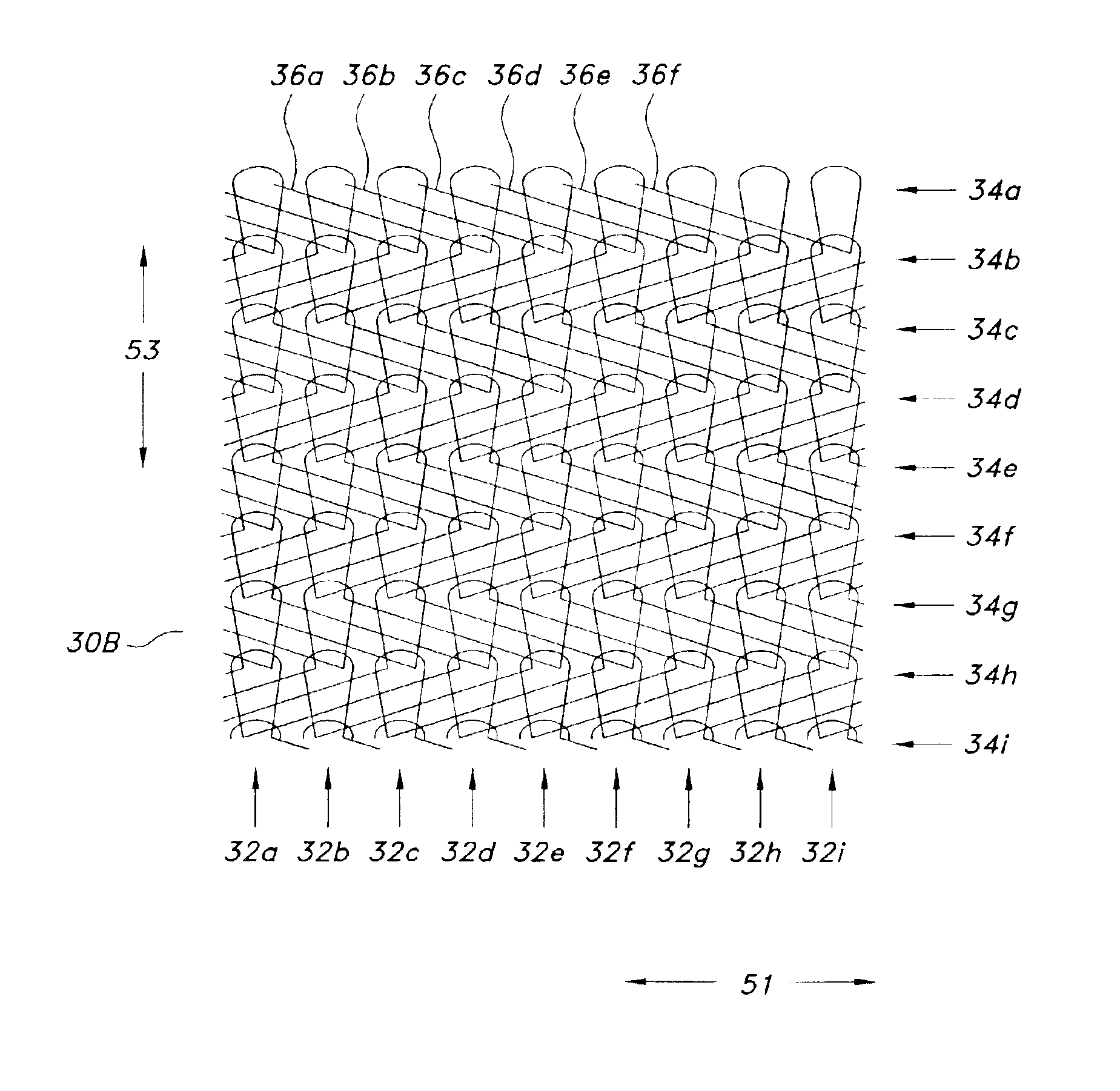
Single Layer Stretch Knit Bifurcated Tubular Graft With a Two-Needle Underlap With Straight Tube (Body or Leg) knitting Details

[0101]The following specifications are used to fabricate a solid knitted prosthesis of the present invention.

[0102]Yarn Type: Texturized polyethylene terephthalate (PET), 40 denier, 27 filaments.

[0103]Machine Type: 60 Gauge Karl Mayer Machine (30 needles per inch).

[0104]Number of Guide Bars: Sixteen

[0105]Guide bars 1-8, if threaded, were used for knitting the front of the graft and guide bars 9-16, if threaded, were used for the rear of the graft.

[0106]

16 Guide Bar Layout:12345678910111213141516GG3-C-45-C-67-C-89-C-1011-C-1213-C-14GGNotes: G: Ground Bars C: Nested Connect Bars

[0107]Guide Bar Threading Details: (Y-Threaded / n-Not Threaded)

[0108]

72 Needle Bifurcated (BIF) Tube or BodyBarNo.Note:←(One Repeat Unit)→#16not usednNnnnnnNnnnn#15nYYYYnnYYYYn#14RYnNnnnnnNnnnY#13CLnNnnnYnNnnnn#12RnNnnnnnNnnYn#11CRnNnnnnYNnnnn#10not usednNnnnnnNnnnn #9not usednNnnnnnNnn...

example 2

Single Layer Knit Tubular Graft With a Three Needle Underlap

[0116]The following specifications are used to fabricate a solid knitted prosthesis of the present invention.

[0117]Yarn Type: Texturized polyethylene terephthalate (PET), 40 denier, 27 filaments.

[0118]Machine Type: 56 Gauge Kiddie Machine (28 needles per inch).

[0119]Number of Guide Bars: Eight

[0120]Guide Bar Threading Details: (y-Threaded / n-Not Threaded)[0121]Guide Bar No. 8: y / y / y / y / y / y / y / y / n / n / n[0122]Guide Bar No. 7: y / n / n / n / n / n / n / n / n / n / n[0123]Guide Bar No. 6: n / n / n / n / n / n / n / n / n / n / y[0124]Guide Bar No. 5: y / n / n / n / n / n / n / n / n / n / n[0125]Guide Bar No. 4: n / n / n / n / n / n / n / n / n / y / n[0126]Guide Bar No. 3: y / n / n / n / n / n / n / n / n / n / n[0127]Guide Bar No. 2: y / n / n / n / n / n / n / n / n / n / n[0128]Guide Bar No. 1: y / y / y / y / y / y / y / y / n / n / n

[0129]Guide Bar Position Details:[0130]Guide Bar No. 1: 6-8-4-4 / 2-0-4-4 / (repeat) Front Full Thread[0131]Guide Bar No. 8: 4-4-2-0 / 4-4-6-8 / (repeat) Back Full Thread[0132]Guide Bar No. 2: 4-6-2-2 / 0-0-0-2 / (repeat) Right Connect[0133]...

example 3

Single Layer Stretch Knit Straight Tubular Graft with a Two-Needle Underlap

[0141]The following specifications were used to fabricate a super stretch knitted prosthesis of the present invention.

[0142]Yarn Type Used: Texturized polyethylene terephthalate (PET), 40 denier, 27 filaments.

[0143]Machine Used: 56 Gauge Kiddie Machine (28 needles per inch)

[0144]Guide Bars Used: 6

[0145]Guide Bar Threading Details: (y-threaded, n-not threaded):

[0146]

Guide BarnnyyyYyyyyynNo. 6Guide BarnynnnNnnnnnnNo. 5Guide BarnnnnnNnnnnnyNo. 4Guide BarnnnnnNnnnnynNo. 3Guide BarynnnnNnnnnnnNo. 2Guide BarnnyyyYyyyyynNo. 1

[0147]Guide Bar Chain Notation Details:

[0148]

Guide Bar No. 1:2-0 / 4-4 / 4-6 / 2-2 / / repeatFront full threadGuide Bar No. 2:4-2 / 4-4 / 2-2 / 2-0 / / repeatLeft connectorGuide Bar No. 3:2-2 / 2-4 / 0-2 / 0-0 / / repeatRight connectorGuide Bar No. 4:0-0 / 0-2 / 2-4 / 2-2 / / repeatRight connectorGuide Bar No. 5:2-0 / 2-2 / 4-4 / 4-2 / / repeatLeft connectorGuide Bar No. 6:2-2 / 4-6 / 2-2 / 2-0 / / repeatBack full thread

Graft Processing:

[0149...


PUM

PropertyMeasurementUnit
thicknessaaaaaaaaaa
thicknessaaaaaaaaaa
thicknessaaaaaaaaaa

Abstract

A radially expandable stent-graft endoprosthesis includes a knitted tubular structure circumferentially disposed and securably attached to the stent. The knitted tubular structure has a warp knit pattern of interlacing yarns with at least a two-needle underlap to provide greater than 50 percent longitudinal stretchability while substantially inhibiting dilation. A knitted tubular graft is combined with an ePTFE liner to form a composite with greater than 50 percent longitudinal stretchability is also provided. The knitted tubular graft also has a warp knit pattern of interlacing yarns with at least a two-needle underlap to provide the longitudinal stretchability while also substantially inhibiting dilation.

Description

CROSS-REFERENCE TO RELATED APPLICATION[0001]The present application is a continuation-in-part of U.S. patent application Ser. No. 10 / 323,569, filed Dec. 19, 2002, which is a continuation of U.S. patent application Ser. No. 09 / 898,103, filed Jul. 3, 2001 now U.S. Pat. No. 6,554,855, the contents of which is incorporated herein by reference.FIELD OF INVENTION[0002]The present invention relates generally to a tubular implantable prosthesis having a knitted textile structure. More particularly, the present invention relates to an endoprosthesis with a knitted textile structure having increased longitudinal stretchability and further having radially restricted enlargement.BACKGROUND OF RELATED TECHNOLOGY[0003]An intraluminal prosthesis is a medical device used in the treatment of diseased blood vessels. An intraluminal prosthesis is typically used to repair, replace, or otherwise correct a diseased or damaged blood vessel. An artery or vein may be diseased in a variety of different ways....

Claims


Application Information

Patent Timeline
Patent Type & Authority Patents(United States)
IPC IPC(8): A61F2/06D04B21/00
CPCA61F2/07D04B21/00A61F2002/065A61F2002/072A61F2002/075A61F2210/0076D10B2509/06A61F2/88A61F2/90A61F2230/0054D10B2401/04D10B2331/04D10B2509/08D04B21/16
Inventor DONG, JERRY Q.
Owner LIFESHIELD SCI
Why Eureka
Try Eureka