Dual mode EGR valve

a technology of exhaust gas recirculation and valve body, which is applied in the direction of machines/engines, mechanical equipment, and non-fuel substance addition to fuel, etc., can solve the problems of compromising performance and difficult implementation of egr on turbocharged engines

Inactive Publication Date: 2005-11-15
CUMMINS INC
View PDF23 Cites 15 Cited by
  • Summary
  • Abstract
  • Description
  • Claims
  • Application Information

AI Technical Summary

Problems solved by technology

Unfortunately, EGR is difficult to implement on turbocharged engines, such as turbocharged diesel engines, for example.
A particular problem is how to obtain sufficient EGR at or near torque peak without compromising performance elsewhere.

Method used


Image

  • Dual mode EGR valve
  • Dual mode EGR valve
  • Dual mode EGR valve

Examples


Embodiment Construction

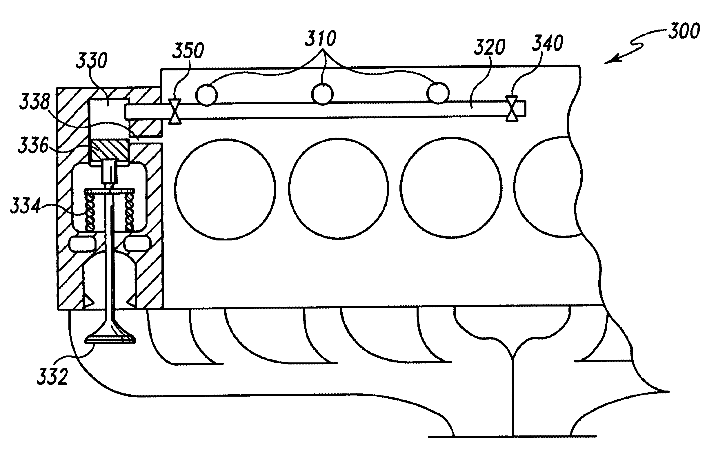
[0026]For the purposes of promoting an understanding of the principles of the invention, reference will now be made to the embodiments illustrated in the drawings and specific language will be used to describe the same. It will nevertheless be understood that no limitation of the scope of the invention is thereby intended, such alterations and further modifications in the illustrated device, and such further applications of the principles of the invention as illustrated therein being contemplated as would normally occur to one skilled in the art to which the invention relates. In particular, although the preferred embodiment is described in the context of a six cylinder, four-stroke engine, it may nonetheless be used with other types of engines with such alterations as will be apparent to those skilled in the art.

[0027]A presently preferred embodiment EGR system according to the present invention has several advantages over the prior art. In particular, a presently preferred embodim...


PUM


Abstract

A preferred embodiment EGR valve permits exhaust gas to be induced into the intake line downstream of the compressor, while minimizing the need to reduce the size of the turbocharger. The preferred embodiment EGR valve exploits variations around the mean pressure in the EGR passage created by the engine cycle by selectively opening when the pressure in the EGR valve exceeds the pressure in the intake line. Thus, exhaust gas is recirculated even when the engine is running near torque peak. The preferred embodiment EGR valve also exploits the higher mean pressure in the exhaust line relative to the intake line at higher engine speeds by remaining open, in order to minimize the energy consumed in opening and closing the EGR valve.

Description

TECHNICAL FIELD OF THE INVENTION[0001]The present invention generally relates to internal combustion engines and, more particularly, to a dual mode exhaust gas recirculation (“EGR”) valve for such engines.BACKGROUND[0002]As is well known in the art, the combustion of hydrocarbon-based fuels in an internal combustion engine produces as a byproduct several undesirable oxides of nitrogen (NOx emissions). The release of such NOx emissions is tightly regulated by governmental authorities in many parts of the world. Exhaust gas recirculation (“EGR”), in which exhaust gases are recirculated to the engine's intake manifold in order to undergo further combustion, is a proven method for reducing NOx emissions. Unfortunately, EGR is difficult to implement on turbocharged engines, such as turbocharged diesel engines, for example. This is because turbocharged engines often have a mean exhaust manifold pressure below the mean intake manifold pressure near peak torque output operating point (“torq...

Claims


Application Information

Patent Timeline
Patent Type & Authority Patents(United States)
IPC IPC(8): F02M25/07
CPCF02M25/0778F02M25/0779F02M25/0789F02M25/0746Y02T10/121F02M26/40F02M26/58F02M26/59F02M26/67
Inventor JANSSEN, JOHN M.WATSON, BRUCE A.SCHENK, CHARLES R.SHAO, JOSH S.PETERS, LESTER L.BUCHANAN, DAVID L.ECKERLE, WAYNE A.PERR, JULIUS P.
Owner CUMMINS INC
Why Eureka
Try Eureka