Number lock device for computer

Inactive Publication Date: 2005-12-13
CHANG CHUN YUAN
View PDF11 Cites 44 Cited by
  • Summary
  • Abstract
  • Description
  • Claims
  • Application Information

AI Technical Summary

Benefits of technology

[0007]The primary objective of the present invention is to provide a number lock device that can be

Problems solved by technology

However, the conventional lock device is operated by the u

Method used


Image

  • Number lock device for computer
  • Number lock device for computer
  • Number lock device for computer

Examples


Example

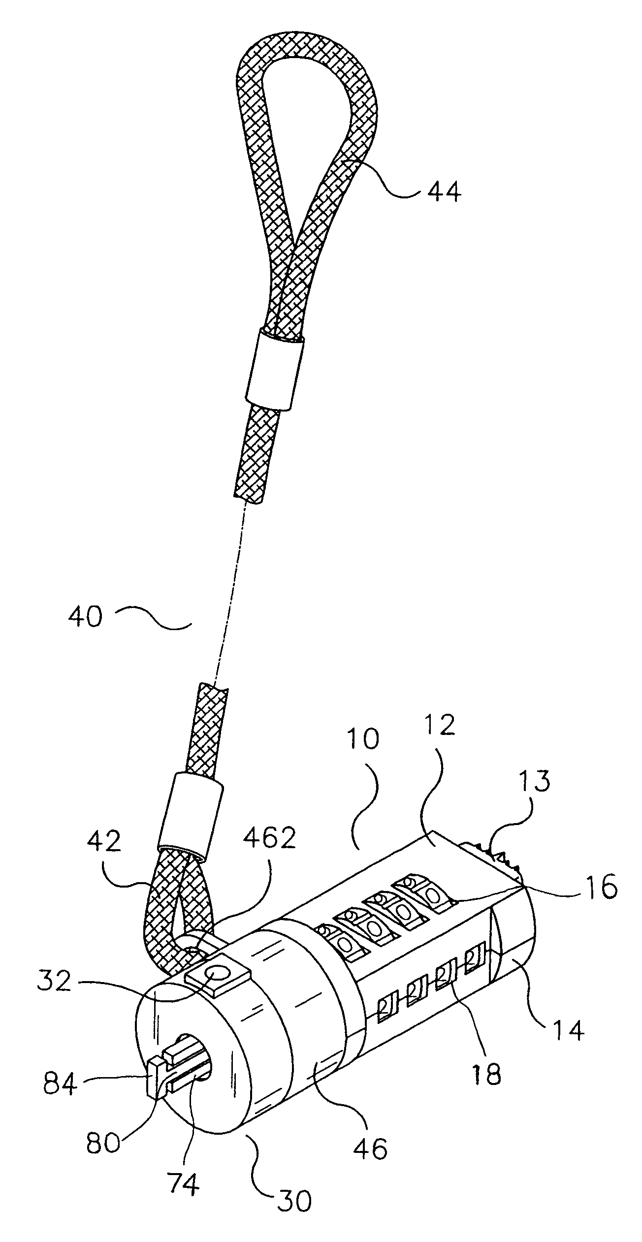
[0032]Referring to the drawings and initially to FIGS. 5–10, a number lock device in accordance with the preferred embodiment of the present invention comprises a lock housing 10, a lock core 20, a cover 30, and a cable 40.

[0033]The lock housing 10 has a first end formed with a pivot sleeve 11 and a second end provided with a movable push button 13. The first end of the lock housing 10 has an inside formed with a receiving chamber 19. The receiving chamber 19 of the lock housing 10 has a wall formed with two opposite elongated guide grooves 192 and two opposite locking grooves 15. The lock housing 10 includes a first shell 12 and a second shell 14 combined with each other. The lock housing 10 has two opposite faces each formed with a plurality of through holes 16 and has a side formed with a plurality of windows 18. The second end of the lock housing 10 is formed with an elongated receiving hole 17 for receiving the push button 13.

[0034]The push button 13 includes a slide 136 (see F...


PUM


Abstract

A number lock device, comprising a lock housing, a lock core, a cable, a cover, a movable member, a driving member, a locking plate, and a locking pin. Thus, the number lock device can be operated by the user's one hand only, thereby facilitating the user operating the number lock device. In addition, the correct numbers of the number rings of the lock core of the number lock device can be changed easily and conveniently.

Description

BACKGROUND OF THE INVENTION[0001]1. Field of the Invention[0002]The present invention relates to a number lock device for locking a computer, and more particularly to a number lock device that can be operated by the user's one hand only, thereby facilitating the user operating the number lock device.[0003]2. Description of the Related Art[0004]A conventional lock device in accordance with the prior art shown in FIGS. 1–4 comprises a housing 1, an inner barrel 2 inserted into the housing 1 and having a distal end having a periphery formed with an outer ring 201 and having an end face formed with a through hole (not shown) for passage of a key (not shown), a mounting ring 4 mounted on the inner barrel 2 located between the housing 1 and the outer ring 201 and provided with a cable 401, and a lock core 3 mounted in the inner barrel 2. The lock core 3 includes a positioning ring 303 having an end face provided with two spaced locking tongues 304 protruding outward from the housing 1, an...

Claims


Application Information

Patent Timeline
IPC IPC(8): E05B73/00
CPCE05B73/0082E05B73/0005Y10T70/40Y10T70/409Y10T70/5009
Inventor CHANG, CHUN-YUAN
Owner CHANG CHUN YUAN
Why Eureka
Try Eureka