

Implant insertion tool
- Summary
- Abstract
- Description
- Claims
- Application Information
AI Technical Summary
Benefits of technology
Problems solved by technology
Method used
Image

Examples
Embodiment Construction
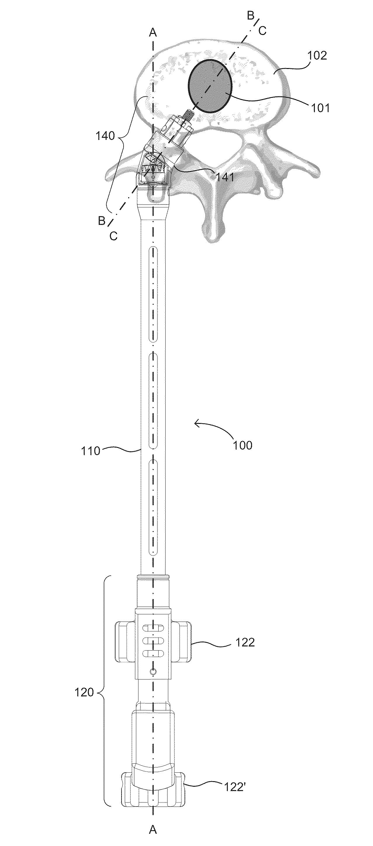
[0025]The present invention is directed to different embodiments of an implant insertion tool. Although the embodiments depicted in FIGS. 1-10 are designed for use with expandable implants disclosed in connection with the tool are in the form of corpectomy cages, it should be understood that the various embodiments disclosed in this application may be utilized with other types of implants. For instance, the present insertion tool might be modified for use with implants other than those shown, which are designed for placement in a single, natural disc space.
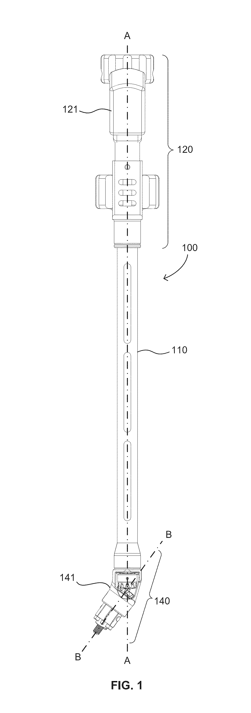
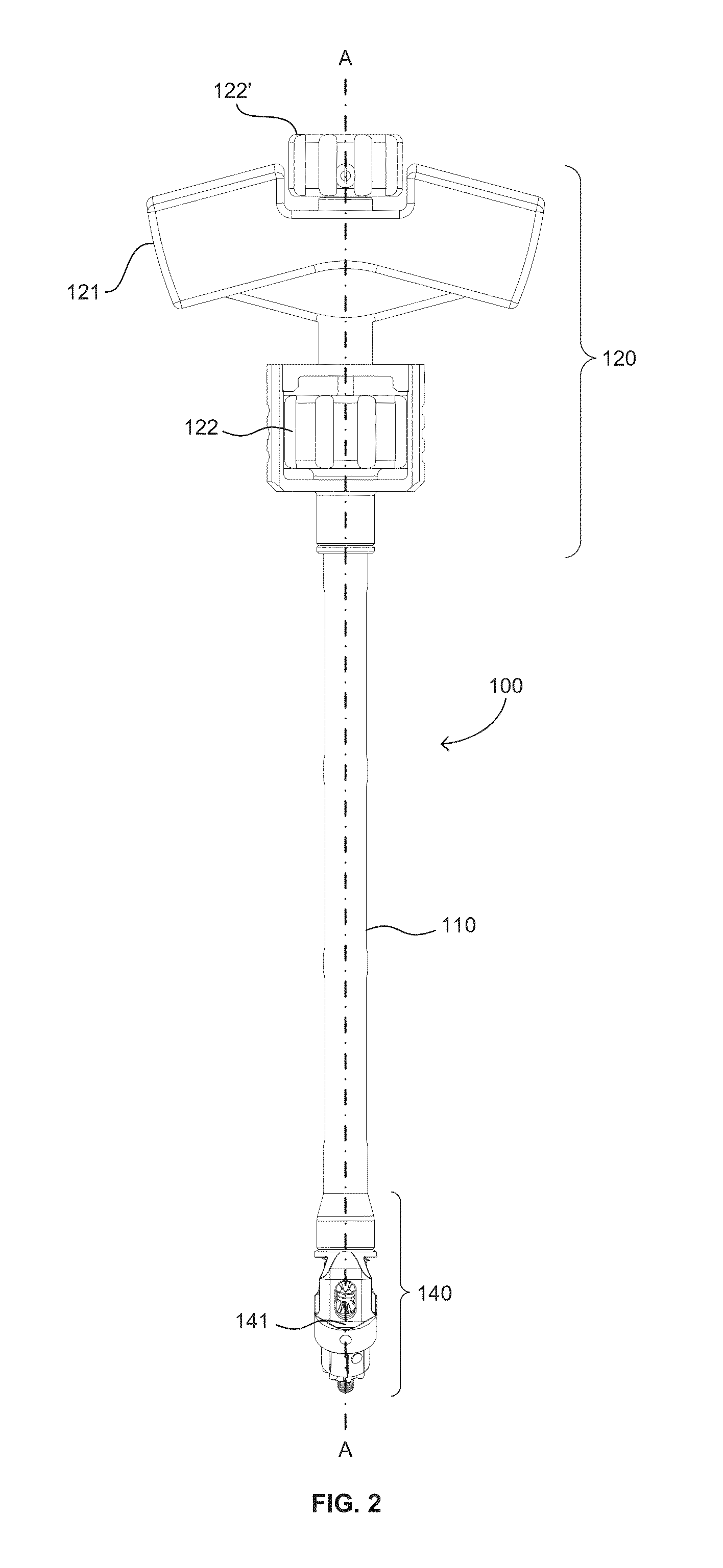
[0026]A first embodiment insertion tool 100 is depicted in FIG. 1. As shown, tool 100 comprises a tube 110 with a handle end 120, an inserter end 140 opposite handle end 120, an outer driveshaft 130 extending within a portion of tube 110, and an inner connecting shaft 130′ extending concentrically within a part of driveshaft 130 (as best shown in FIG. 3). Inserter end 140 includes a curved portion 141 to permit insertion of an imp...
PUM
 Abstract
Description
Claims
Application Information