
Inflatable satellite bus

Active Publication Date: 2005-11-08
BIGELOW AEROSPACE
View PDF11 Cites 25 Cited by
  • Summary
  • Abstract
  • Description
  • Claims
  • Application Information

AI Technical Summary

Benefits of technology

[0007]The inflatable satellite bus is comprised of a core and an inflatable shell attached to the core. The core has an internal volume that is adapted to receive payloads including mission specific payloads. There is also an attitude control device coupled to the core, a power source coupled t

Problems solved by technology

While such an approach supports a standard that satellite manufactures may rely upon in

Method used


Image

  • Inflatable satellite bus
  • Inflatable satellite bus
  • Inflatable satellite bus

Examples


Example

DETAILED DESCRIPTION OF THE DRAWINGS

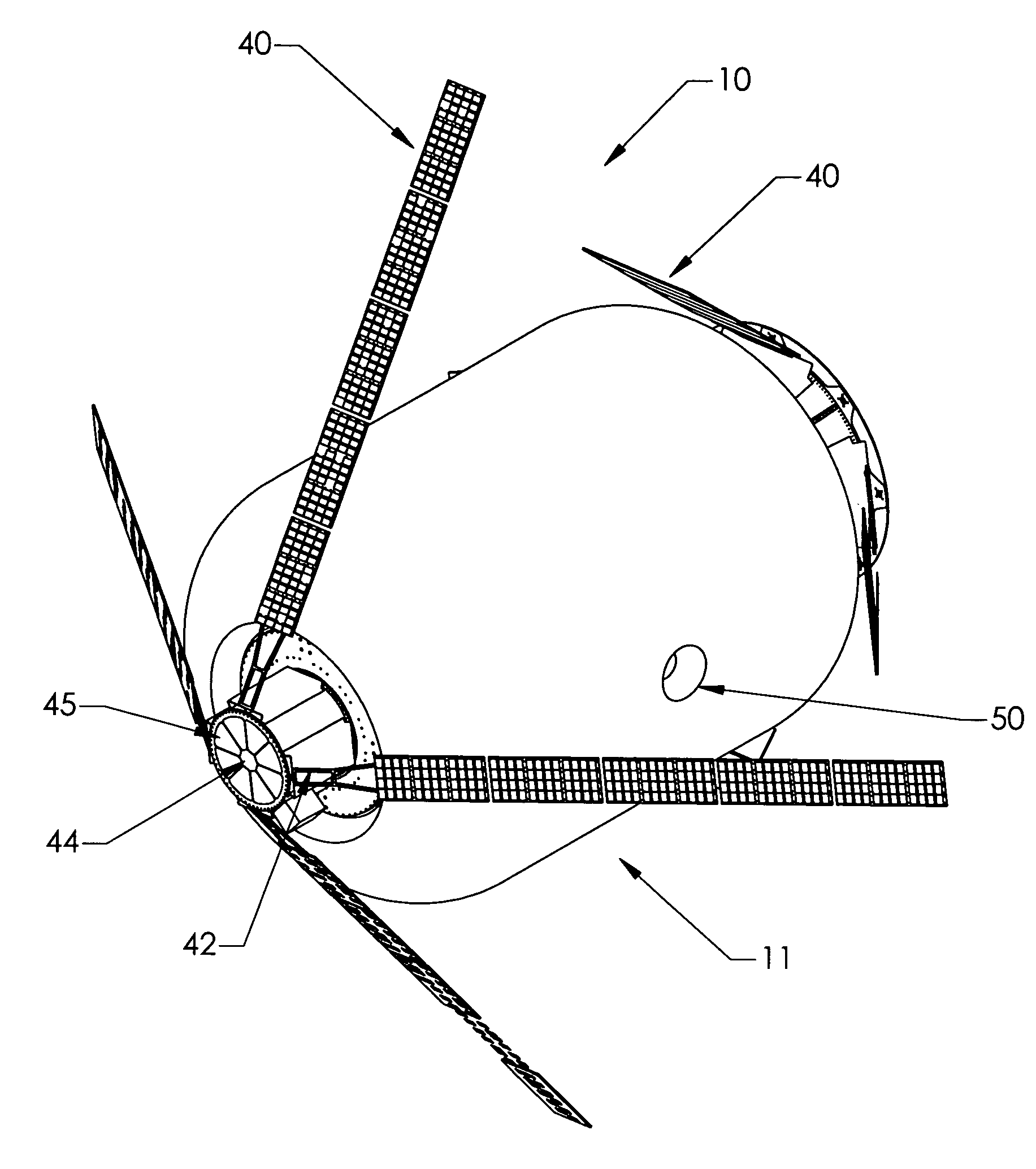
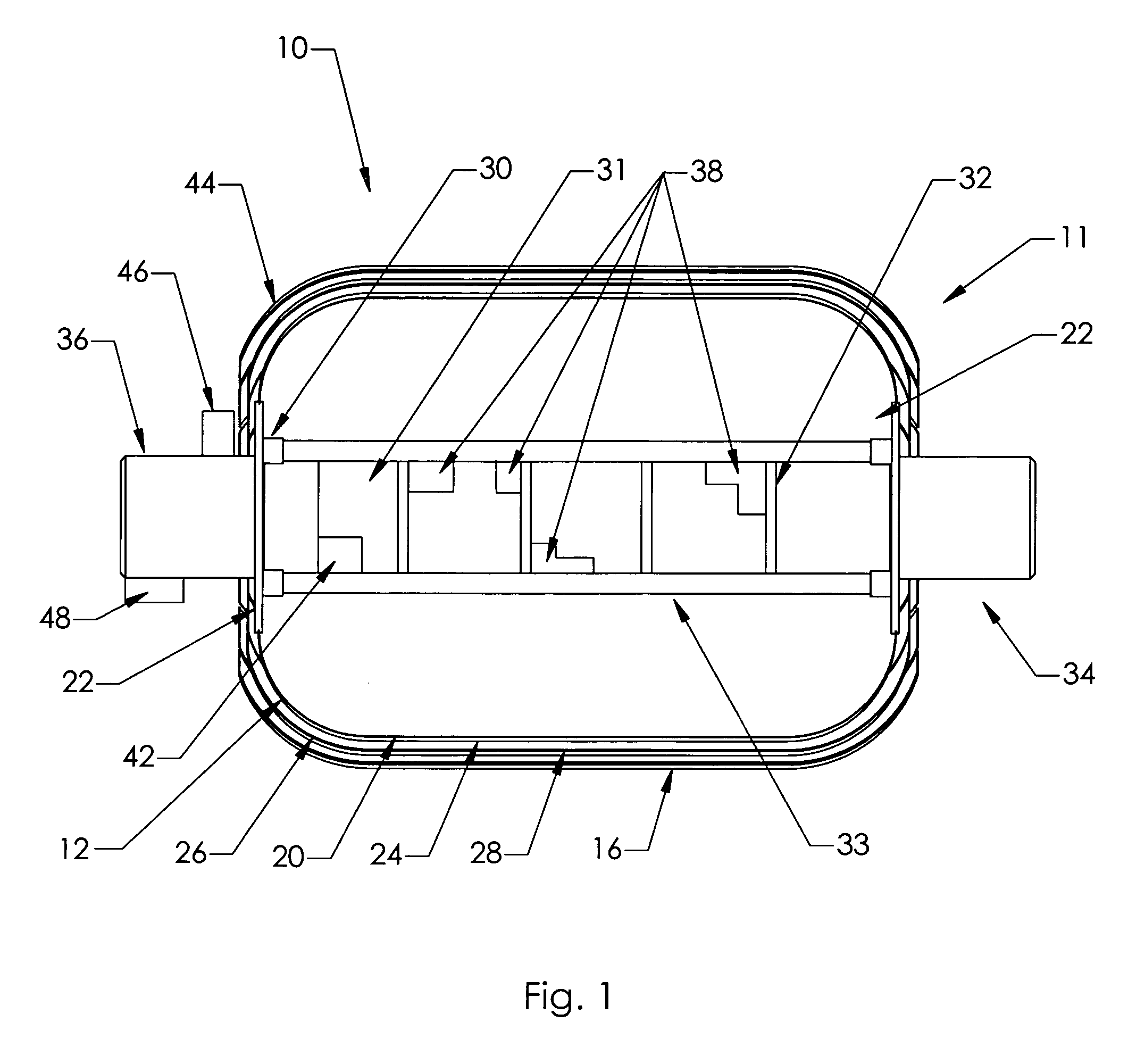
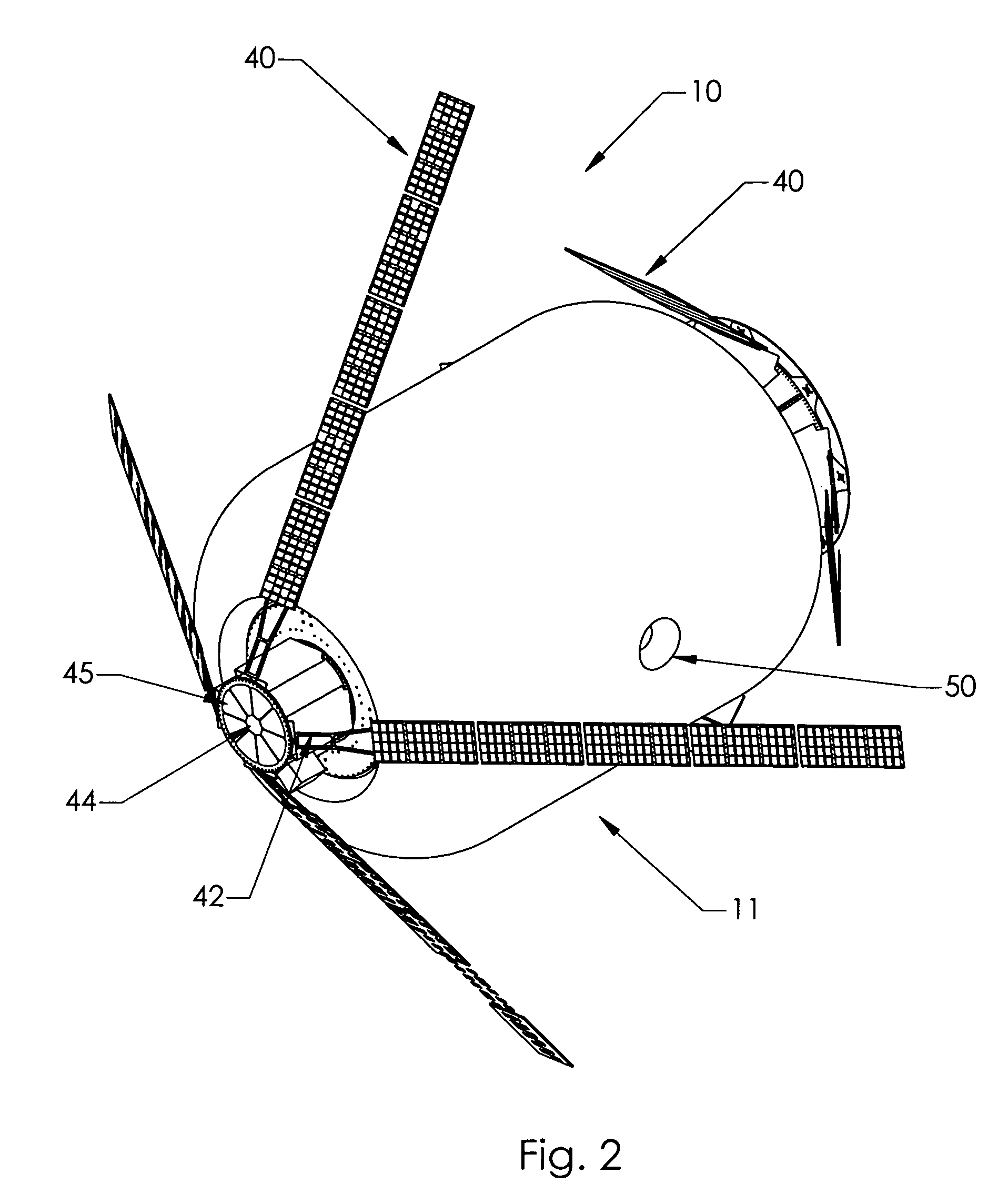
[0010]The present invention may best be understood by reference to the following description taken in conjunction with the accompanying drawings. FIG. 1 is a cross-sectional side view of an inflated satellite bus 10. The bus is not restricted to a particular size, or shape, as evidenced by the bus in FIG. 1 being large enough to house individuals. This size bus can be used as a platform for a number of satellite missions or as a master satellite to control the operation of other satellites. Illustrated in this figure is the inflatable shell 11. The shell 11 is flexible and there are several variations on the shell including, for example, a variety of flexible meteor shields. In the preferred embodiment, the shell 11 is comprised of an air bladder 12, a meteor shield 14, and a restraint layer 16. Such configurations are known in the art.

[0011]The air bladder 12 is a substantially non-permeable material that prevents the gas inside the craft from es...


PUM


Abstract

An inflatable satellite bus is claimed for use with a mission payload. The inflatable satellite bus is comprised of a core adapted to receive a mission payload. There is an expandable shell attached to the core and substantially enclosing the core. The core has an attitude control device and a power system attached to the core and operated by a controller.

Description

BACKGROUND OF THE INVENTION[0001]1. Field of the Invention[0002]This invention relates to an inflatable satellite bus for use with mission payloads.[0003]2. Description of the Prior Art[0004]Many satellites are composed of two main elements; the payload and the bus. The payload contained the equipment that was mission specific to the satellite's intended purpose. The bus provided support functions common to most satellites such as attitude control, power, and telemetry.[0005]The separation of functions common to most satellites into a bus allowed for the development of a standard base to support a variety of satellites. One advantage to a standard bus is that the bus affords a known footprint for the satellite payload. While such an approach supports a standard that satellite manufactures may rely upon in preparing a payload, the footprint becomes a limiting factor in the design of satellites.[0006]What is needed is a satellite bus that provides a more flexible base for the payload....

Claims


Application Information

Patent Timeline
IPC IPC(8): B64G1/00B64G1/10B64G1/12B64G1/42B64G1/44B64G1/56
CPCB64G1/10B64G1/1007B64G1/1021B64G1/12B64G1/422B64G1/423B64G1/443B64G1/56B64G2001/224B64G1/2227
Inventor BIGELOW, ROBERT T.
Owner BIGELOW AEROSPACE
Learn More