Compressor and assembly method thereof

Active Publication Date: 2012-09-27
MITSUBISHI HEAVY INDUSTIES COMPRESSOR
View PDF4 Cites 23 Cited by
  • Summary
  • Abstract
  • Description
  • Claims
  • Application Information

AI Technical Summary

Benefits of technology

[0022]In this way, with a compressor according to the present invention and a method of assembling the same, it is possible, with a simple configuration, to facilitate the insertion operation of a compressor bundle by reliably preventing tilting thereof du

Problems solved by technology

However, with a recent increase in the size of compression equipment, there are now 100-ton class compressor bundles, and it is very difficult to accommodate such a heavy compressor bundle in a chamber by sliding it thereinto.
Because of this, if the compressor bundle tilts toward the chamber even s

Method used


Image

  • Compressor and assembly method thereof
  • Compressor and assembly method thereof
  • Compressor and assembly method thereof

Examples


Example

[0029]An embodiment of the present invention will be described below with reference to FIGS. 1 to 4.

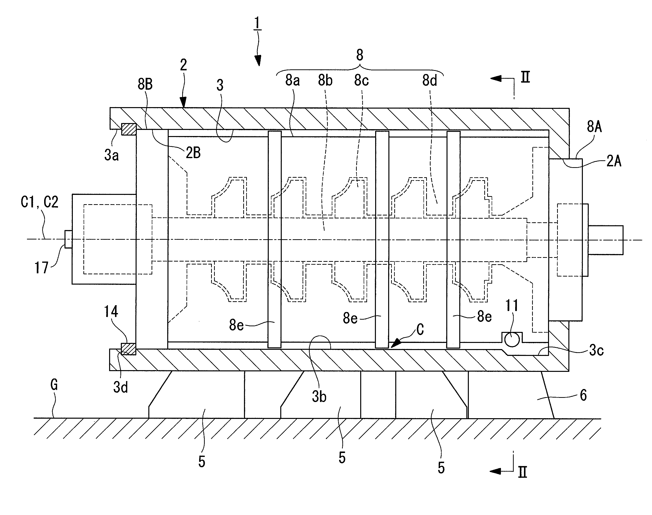
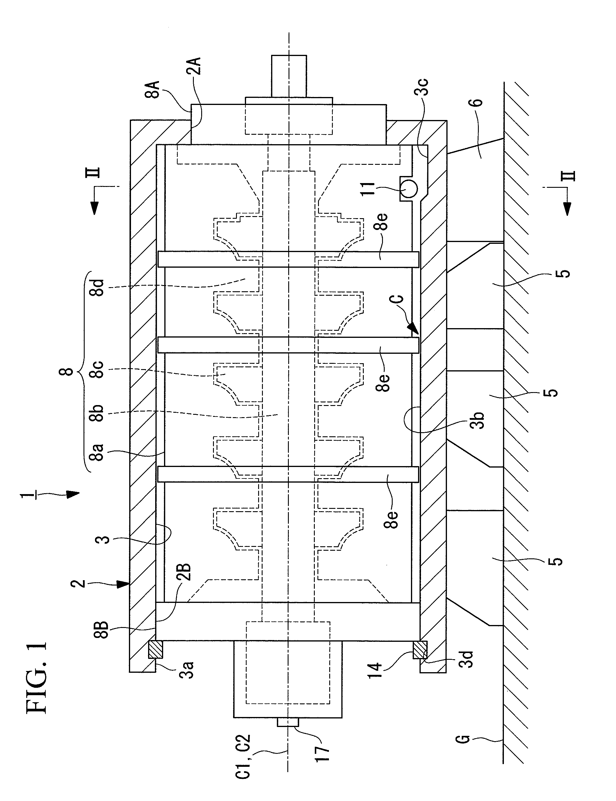
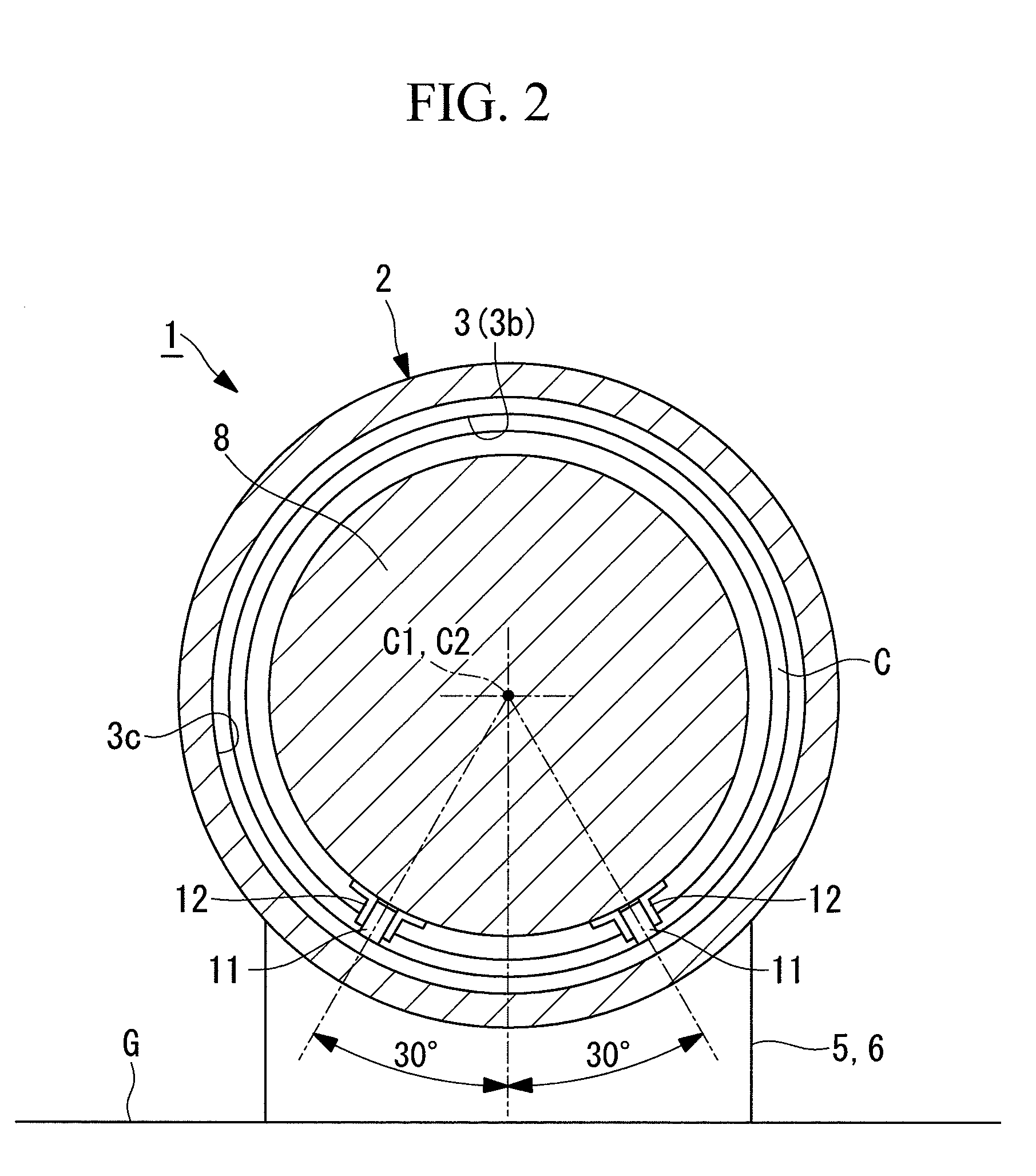
[0030]As shown in FIGS. 1 and 2, a compressor 1 according to the embodiment of the present invention is provided with a substantially cylindrical bundle casing 2, and a substantially cylindrical chamber 3 is formed thereinside. The rear end (the left side when viewing FIG. 1) of the chamber 3 opens widely as a bundle insertion opening 3a. By means of a plurality of intake nozzles 5, a single discharge nozzle 6, support leg members (not shown), etc., this bundle casing 2 is set so as to be at a predetermined height with respect to an installation surface G and also so that a center axis C1 of the chamber 3 becomes horizontal.

[0031]A compressor bundle 8 is inserted into the chamber 3 of the bundle casing 2 from the bundle insertion opening 3a, that is, from rear to front in the axial direction. This compressor bundle 8 has a known basic configuration in which a rotor 8b, which is a main...


PUM

PropertyMeasurementUnit
Weightaaaaaaaaaa
Pressureaaaaaaaaaa
Angleaaaaaaaaaa

Abstract

Provided is a compressor that is capable of, with a simple configuration, facilitating the insertion operation of a compressor bundle by reliably preventing tilting thereof during insertion into a chamber; and that also makes it possible to reduce a roller size without increasing the contact pressure of rollers for sliding the compressor bundle. A small tilt sensor that detects a relative angle difference θ of the compressor bundle with respect to the bundle casing is provided at at least one location in the compressor bundle to be inserted into the chamber inside the bundle casing. In addition, the weight of the compressor bundle during the insertion into the chamber is supported by rollers provided at a bottom portion near the front end of the compressor bundle by making the rollers come in contact with an inner circumferential wall surface of the chamber.

Description

CROSS-REFERENCE TO RELATED APPLICATIONS[0001]This application is based on Japanese Patent Application No. 2010-093293, the contents of which are incorporated herein by reference.TECHNICAL FIELD[0002]The present invention relates to a compressor that is formed by accommodating a cylindrical compressor bundle, in which a rotor, rotor blades, and stator blades are included inside a bundle housing, in a cylindrical chamber formed inside a bundle casing and to a method of assembling the same.BACKGROUND ART[0003]In this type of compressor, with conventional units having compressor bundles whose weight is in up to about 20-ton class, the compressor bundle is inserted into a chamber by sliding it thereinto from an opening provided at one end of the chamber. However, with a recent increase in the size of compression equipment, there are now 100-ton class compressor bundles, and it is very difficult to accommodate such a heavy compressor bundle in a chamber by sliding it thereinto. Because of...

Claims


Application Information

Patent Timeline
IPC IPC(8): F04D29/64F04D19/00B23P15/00F04D29/52
CPCF04D17/122Y10T29/49236F04D29/624
Inventor SASAKI, MASASHIYOSHIMI, TAKESHITOZAKI, YASUYOSHIYANO, AKIHIKOHIGASHIO, ATSUSHI
Owner MITSUBISHI HEAVY INDUSTIES COMPRESSOR
Why Eureka
Try Eureka