Mixer with pivotable bowl

a technology of mixer and pivotable bowl, which is applied in the direction of mixer, rotary stirring mixer, transportation and packaging, etc., can solve the problems that users may have difficulty in accessing the bowl to add or remove materials from the bowl, and achieve the effect of quick and easy coupling

Inactive Publication Date: 2006-01-31
PREMARK FEG L L C
View PDF87 Cites 19 Cited by
  • Summary
  • Abstract
  • Description
  • Claims
  • Application Information

AI Technical Summary

Benefits of technology

[0006]The present invention is a mixer having a bowl that is pivotally coupled to the mixer body. The pivotable nature of the bowl enables the bowl to pivot away from the mixer body, which provides convenient access to the bowl. The bowl can also be quickly and easily coupled to, and uncoupled from, the mixer body.

Problems solved by technology

However, even after the bowl is lowered, the user may have difficulty in accessing the bowl to add or remove materials from the bowl due to the location and orientation of the overhang portion of the mixer body relative to the bowl.

Method used


Image

  • Mixer with pivotable bowl
  • Mixer with pivotable bowl
  • Mixer with pivotable bowl

Examples


Embodiment Construction

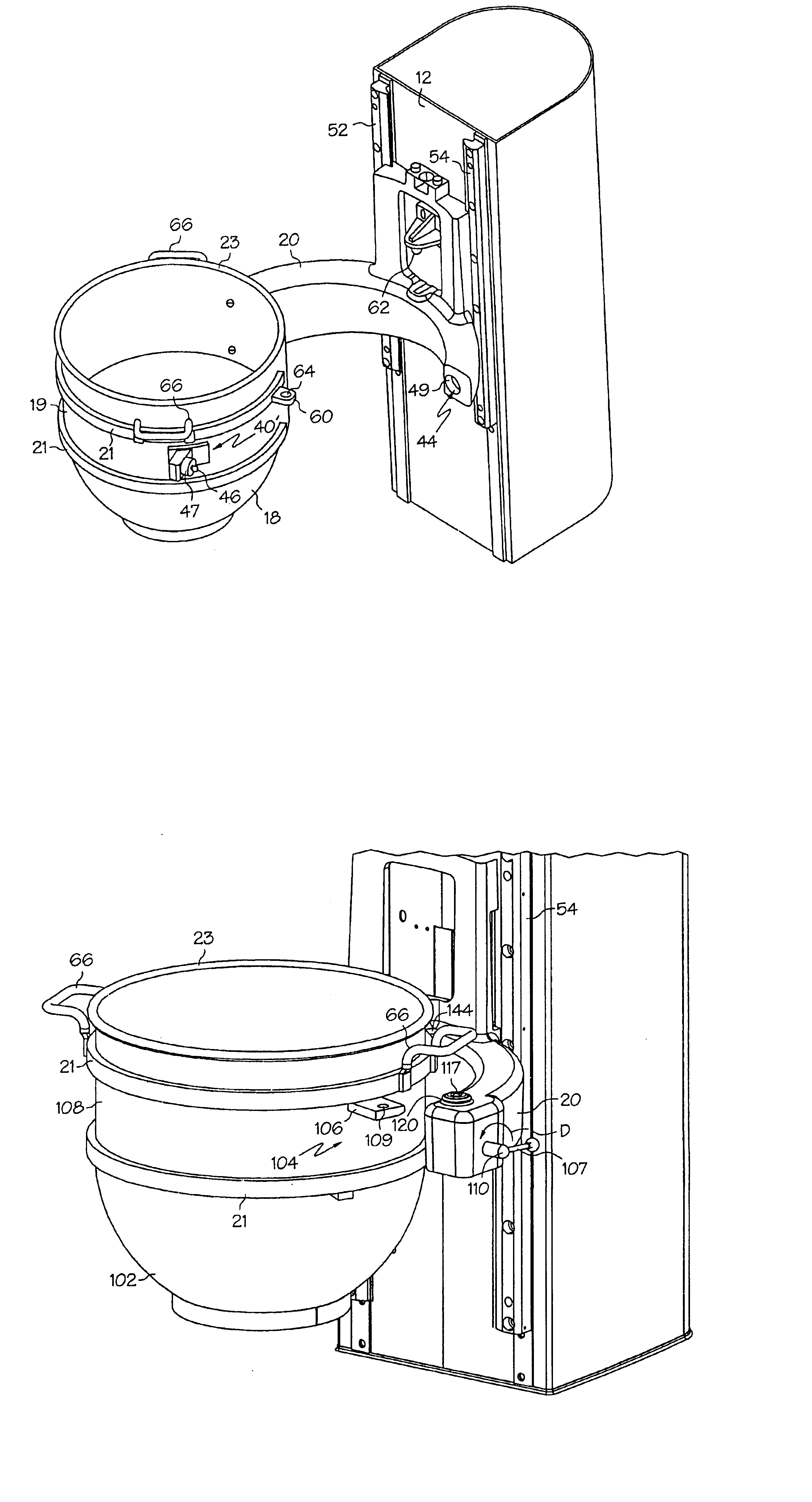
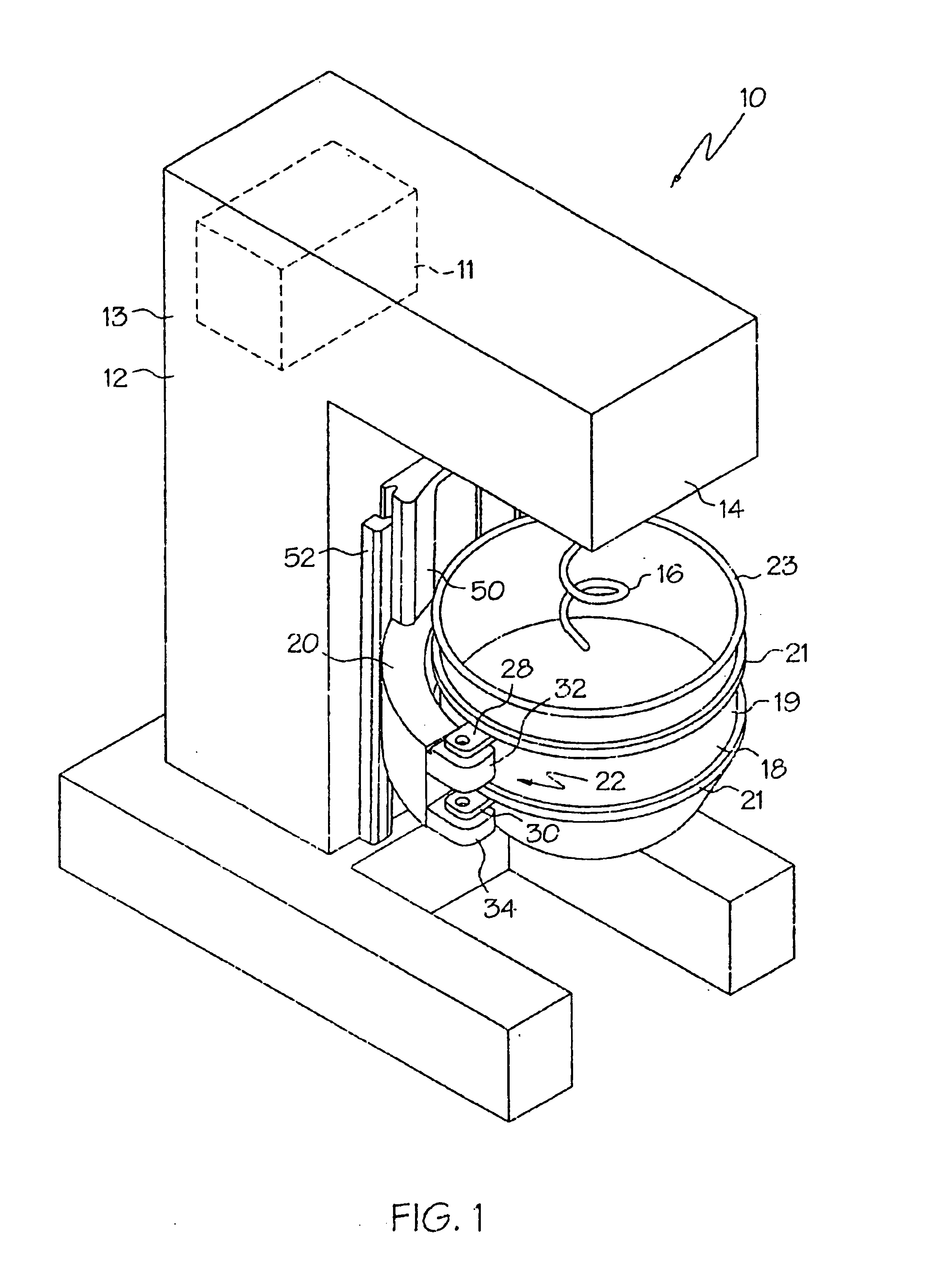
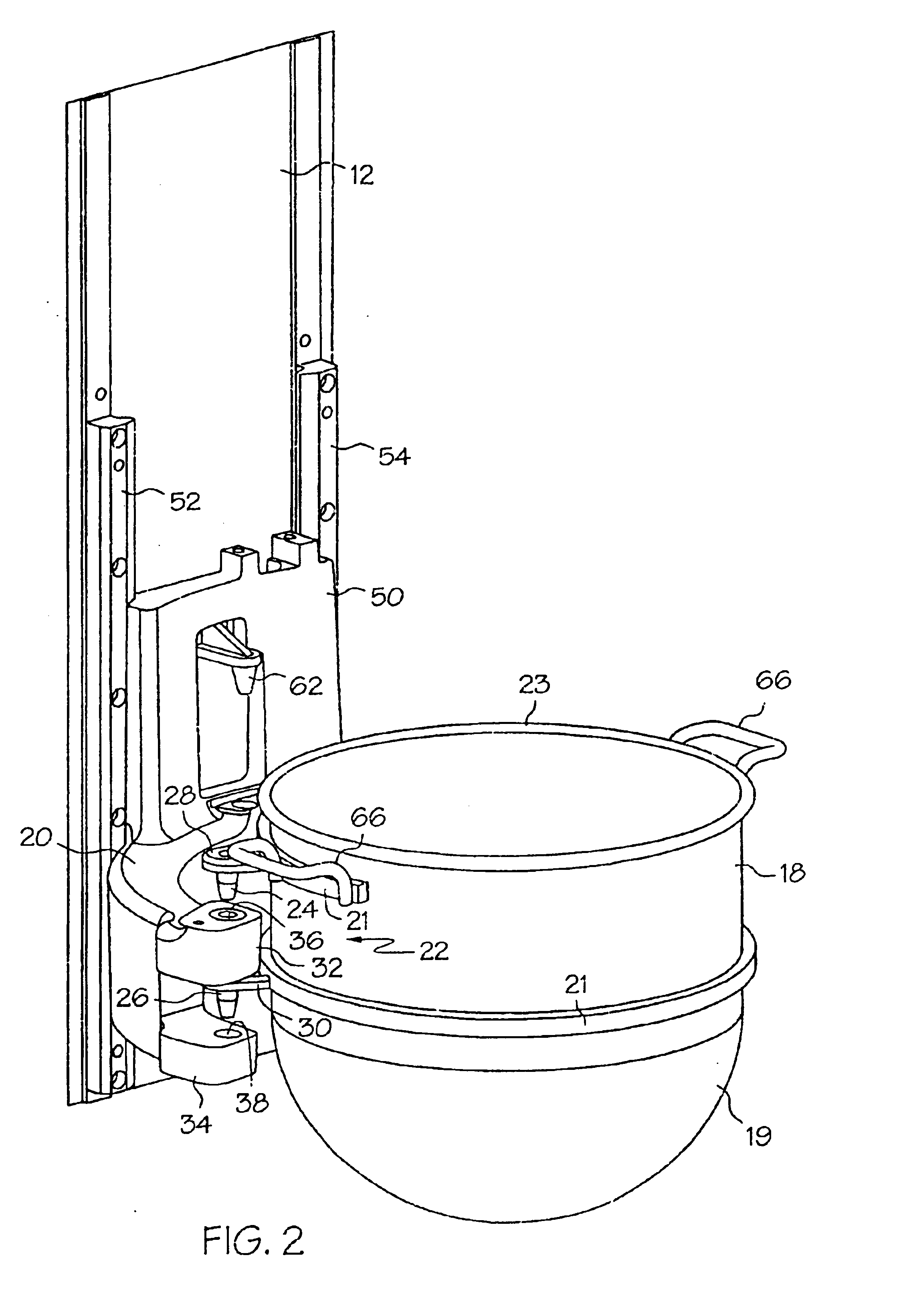
[0029]FIG. 1 illustrates a mixer, generally designated 10, which includes a mixer body 12 having a generally vertically-extending main portion 13 and a overhang portion or transmission head 14. The mixer body 12 includes a yoke 20 coupled to the main portion 13 of the mixer body 12. The yoke 20 is generally semicircular in top view, and is shaped to closely receive a mixer bowl 18 therein. The yoke 20 is coupled to a vertically movable yoke base 50, and the yoke base 50 is vertically movable along a pair of guide rails 52, 54.

[0030]The mixer 10 includes a motor or mixing drive 11 housed in the mixer body 12. The mixing drive 11 is drivingly coupled to an output component 15 (see FIG. 8) to rotate the output component about its central axis A. The mixer 10 includes a generally downwardly-extending mixing element 16 (such as a dough hook) that is removably connected to the output component 15. The mixing element 16 can be any of a wide variety of shapes and can be coupled to the outpu...


PUM


Abstract

A pivotable mixer bowl including a bowl body for receiving material to be mixed, a first mounting bracket coupled to and extending from an outer surface of the bowl body and having an opening therein, and a second mounting bracket coupled to and extending from the outer surface and having an opening therein. The second mounting bracket is vertically spaced from the first mounting bracket. The opening of the second mounting bracket is generally aligned with the opening of the first mounting bracket to define a pivot axis of the mixer bowl. The mixer bowl further includes a locking bracket coupled to and extending from an outer surface of the bowl body.

Description

[0001]This application is a continuation-in-part of U.S. application Ser. No. 09 / 561,828, filed Apr. 28, 2000, now U.S. Pat. No. 6,494,610 B1, the contents of which are hereby incorporated by reference.BACKGROUND OF THE INVENTION[0002]The present invention is directed to a bowl that can be pivotally coupled to a mixer, and to a mixer system having a pivotable bowl.[0003]Mixers are used to mix and blend a wide variety of materials. The mixers typically include a mixer body having a motor that drives a generally vertically-extending mixing element, and a bowl that is located below the mixing element. The bowl receives the materials to be mixed and the lower end of the rotatable mixing element therein. The bowl is typically detachable from the mixer body to aid in loading and unloading the materials into the bowl, and to enable cleaning, repair or replacement of the bowl.[0004]In most existing mixers, the mixer bowl is vertically movable relative to the body such that the bowl can be l...

Claims


Application Information

Patent Timeline
Patent Type & Authority Patents(United States)
IPC IPC(8): B01F13/00B01F7/16A21C1/02A47J43/07B01F7/00B01F15/00B01F15/02
CPCA21C1/02A47J43/0727B01F15/00733B01F15/0295B01F7/1605B01F7/00566B01F2215/0026B01F15/0266B01F27/119B01F27/805B01F35/42B01F35/75B01F35/7548B01F2101/1805
Inventor BRUNSWICK, BRIAN A.HUANG, JOSEPH C.BADER, BRIAN E.
Owner PREMARK FEG L L C
Why Eureka
Try Eureka