Self locking coupling device

Active Publication Date: 2007-04-12
MACDON INDS
View PDF22 Cites 2 Cited by
  • Summary
  • Abstract
  • Description
  • Claims
  • Application Information

AI Technical Summary

Benefits of technology

[0005] It is an object of the present invention to provide a coupling device that can connect to a coupling member in a locking fashion without requiring manual actuati

Problems solved by technology

However, the invention requires accurate placement of the upper link such that the movable jaw is positioned directly over the coupling pin, which de

Method used


Image

  • Self locking coupling device
  • Self locking coupling device
  • Self locking coupling device

Examples


Example

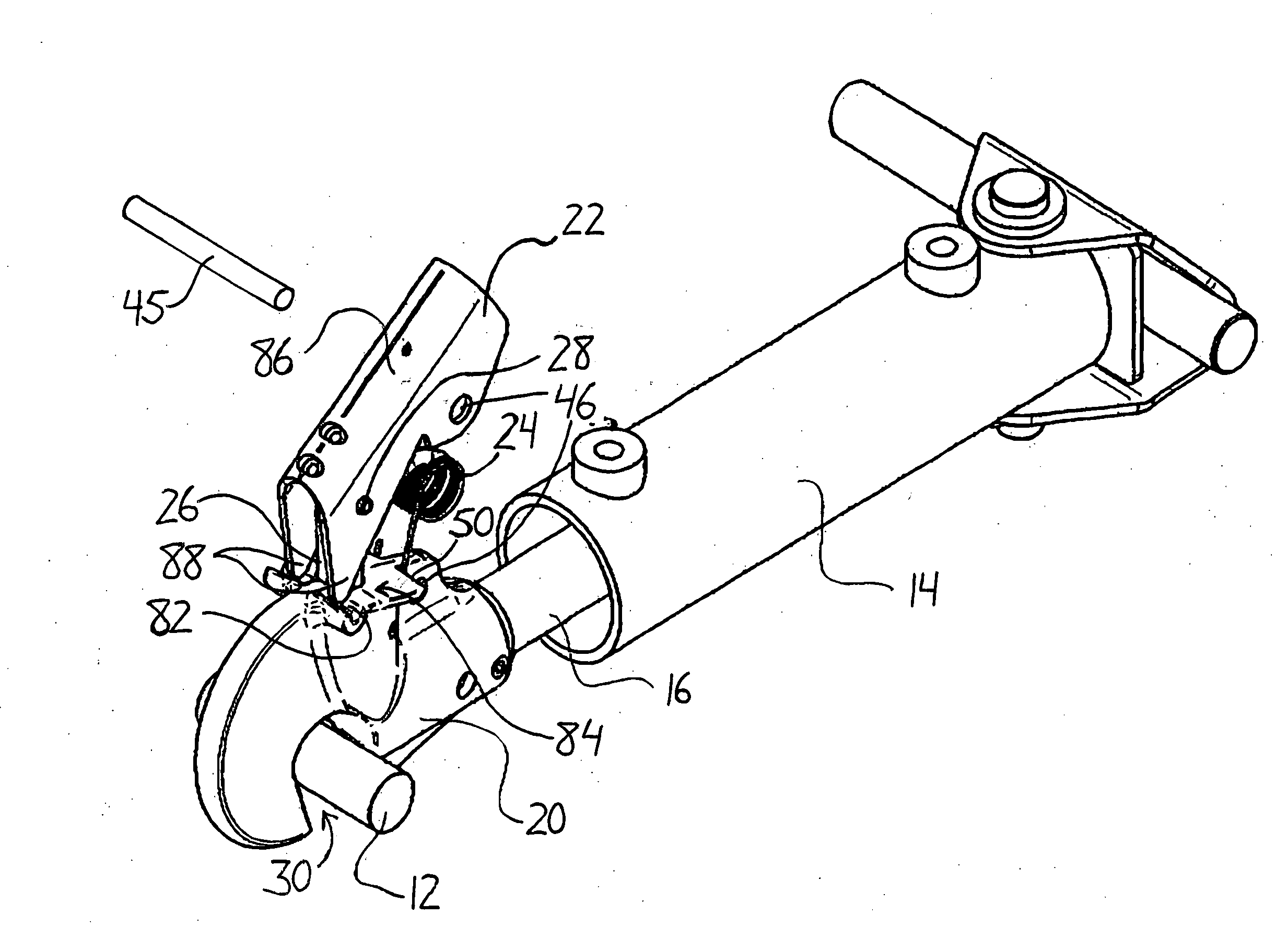
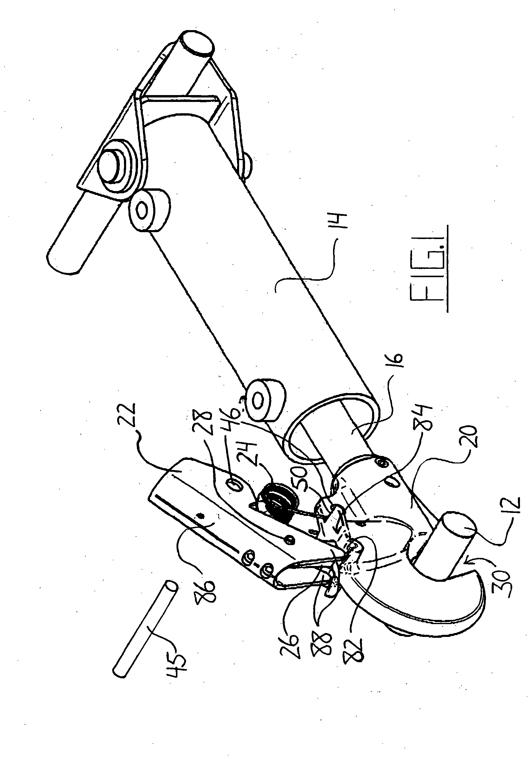
[0035] As shown in FIG. 1, the coupling device 10 of the present invention is arranged to connect a vehicle, such as a tractor or combine, on which it is mounted to an implement having a coupling pin 12. The device 10 features a hydraulic cylinder having a body 14 and a rod 16 which extends away from the vehicle. A hook body 20 is mounted at an end of the rod 16 opposite the cylinder body 14. At the top of the hook body 20 is a control lever 22 that is attached to the hook body 20 by a torsion spring 24. The control lever 22 is connected to a locking bolt 26 at a pivot point 28 and is used to control the position of the locking bolt 26 that extends vertically downward through the hook body into a mouth 30 of the hook body 20 where the coupling pin 12 is received. The position of the locking bolt 26 determines whether or not the coupling pin 12 is locked within the mouth 30.

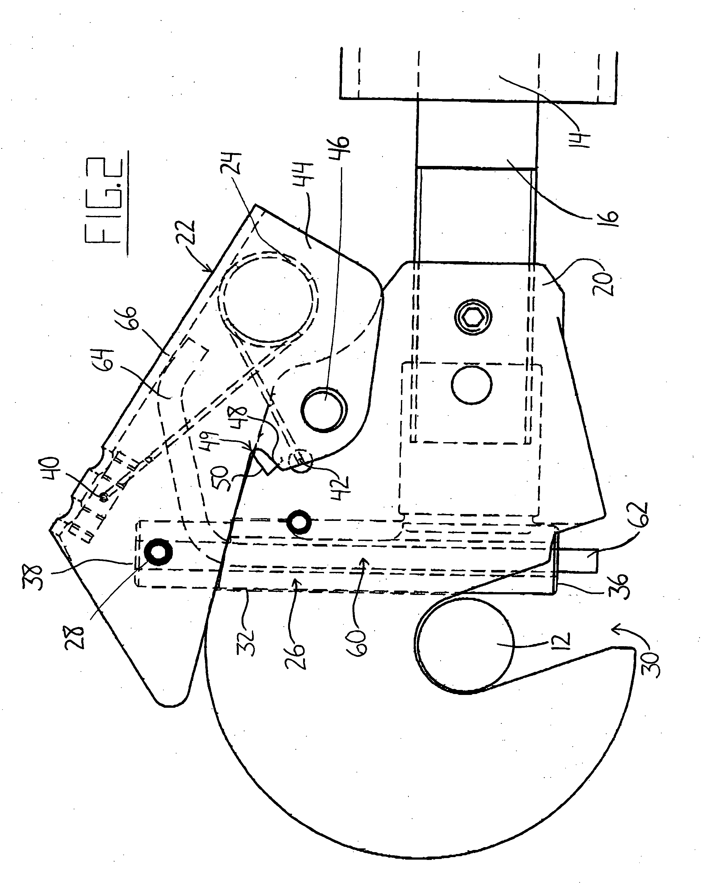
[0036]FIG. 2 shows the device 10 with the coupling pin 12 received in the mouth 30, the locking bolt 26 in a l...


PUM


Abstract

A coupling device that requires no manual actuation to achieve coupling features a locking bolt movable along a hole extending into a mouth of a hook body to secure a coupling pin therein. A control lever pivotally connected to the locking bolt opposite the mouth end is biased toward a locked position in which motion of the locking bolt is blocked. To engage the coupling pin and the hook mouth, the coupling pin and an operable pin extending through the hollow locking bolt are brought into contact. This causes an end of the operable pin opposite the mouth to push against the control lever to unlock it from the latching position. The coupling pin pushes the locking bolt out of the mouth so that it can pass by further into it, at which point the lever and bolt return to the locked positions to secure the coupling pin inside.

Description

[0001] This invention relates to a coupling device that locks to a coupling member or member to be hooked to prevent inadvertent separation of the two and more particularly to a self locking coupling device that can receive and lock the coupling member in the mouth of a hook without manual actuation of its locking components. BACKGROUND OF THE INVENTION [0002] Removable coupling devices such as hooks are commonly used to temporarily connect two separate objects. Often, it is necessary or desirable to provide a removable connection that can be locked in order to ensure that the two objects are not inadvertently separated before it is desirable to do so. For example, three-point hitch systems for tractors and other agricultural vehicles often feature an upper link having a hook that operates in a locking fashion to prevent detachment of an implement from the vehicle during its use. While described in this context, the present invention is not intended to be limited to this particular ...

Claims


Application Information

Patent Timeline
IPC IPC(8): B60D1/00
CPCB60D1/04Y10T24/45382B60D1/28Y10T292/0969Y10T292/432
Inventor PATTERSON, ROGER L.
Owner MACDON INDS
Why Eureka
Try Eureka