Circuit Breaker Lockout Device

a circuit breaker and lockout device technology, applied in the direction of electric switches, basic electric elements, electric apparatus, etc., can solve the problems of circuit breaker lockout devices that cannot be readily removed from the circuit breaker, and the switch of the circuit breaker cannot be freely rotated, so as to achieve quick and easy coupling, greatly improve warehouse or factory efficiency, and facilitate uncoupling

Active Publication Date: 2019-07-18
BRADY WORLDWIDE INC
View PDF0 Cites 3 Cited by
  • Summary
  • Abstract
  • Description
  • Claims
  • Application Information

AI Technical Summary

Benefits of technology

[0007]The present disclosure provides a circuit breaker lockout device that can be quickly and easily coupled to a variety of differently-sized circuit breakers. The circuit breaker lockout device can be secured to a circuit breaker and locked out in accordance with OSHA regulations using a variety of different lock types and sizes. When secured to a circuit breaker and properly locked out using the shackle (or other component) of a lock, the switch of the circuit breaker cannot be freely rotated and the circuit breaker lockout device cannot be readily removed from the circuit breaker without first removing the lock from the circuit breaker lockout device. A biasing element within the circuit breaker lockout device selectively allows rotational movement of a fastener used to couple the circuit breaker lockout device to the circuit breaker. The biasing element allows the circuit breaker lockout device to quickly transition between a closed position (where the circuit breaker lockout device is securely coupled to a circuit breaker) and an open position (and vice versa) that allows the circuit breaker lockout device to be readily uncoupled from a circuit breaker by hand. Using the disclosed circuit breaker lockout device, warehouse or factory efficiency can be greatly improved.
[0010]In another aspect, the circuit breaker lockout device includes an arm and a fastener extending through the arm that together engage and secure the lockout device to a circuit breaker. The arm is partially received within an outer housing, which is movable relative to the arm between an open position and a closed position. A biasing element is positioned between the arm and the outer housing, and allows the outer housing to be resiliently displaced relative to the arm to a closed position, where a locking aperture formed through the arm is exposed from the outer housing. When exposed from the outer housing, a lock shackle can be passed through the locking aperture to prevent the outer housing from returning to its resting, open position relative to the arm. When a lock shackle is passed through the locking aperture, a head of the fastener is at least partially received within the walls of the outer housing, which together prevent rotation of the fastener that could unsecure the circuit breaker lockout device from the circuit breaker. Once the lock shackle is removed, the biasing element urges the outer housing back to an open position, exposing the head of the fastener from the outer housing. Once exposed from the outer housing, the head of the fastener can be rotated to uncouple the circuit breaker lockout device from the circuit breaker.

Problems solved by technology

When secured to a circuit breaker and properly locked out using the shackle (or other component) of a lock, the switch of the circuit breaker cannot be freely rotated and the circuit breaker lockout device cannot be readily removed from the circuit breaker without first removing the lock from the circuit breaker lockout device.

Method used


Image

  • Circuit Breaker Lockout Device
  • Circuit Breaker Lockout Device
  • Circuit Breaker Lockout Device

Examples


Embodiment Construction

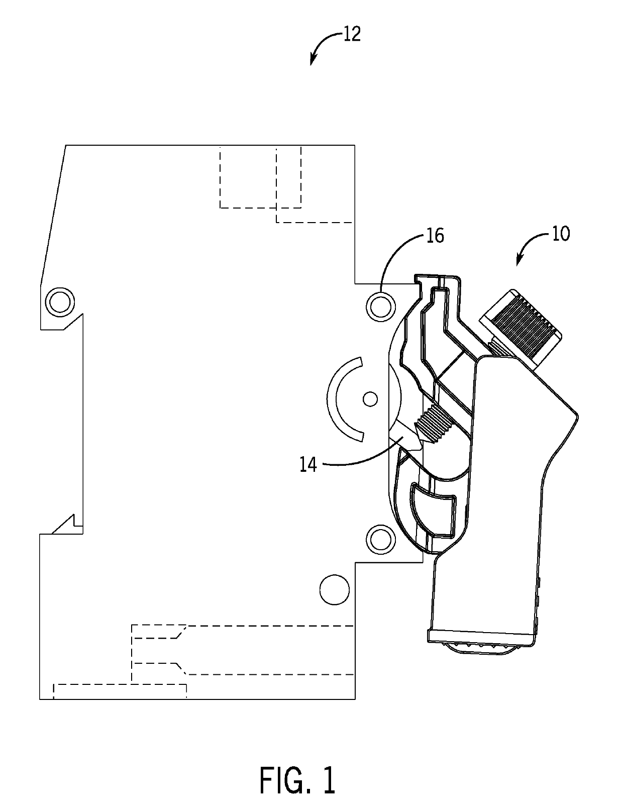
[0023]Generally, the present disclosure provides devices and methods for locking out a circuit breaker. When installed, the lockout devices can be secured to the circuit breaker switch and can engage the circuit breaker body to prevent rotation of the circuit breaker switch relative to the circuit breaker body.

[0024]For purposes of clarity, the foregoing figures will be described using terms such as “rear,”“back,”“front,”“top,”“bottom,”“right,”“left,”“side,”“downward,”“upward,” or other types of directional language. The directional language used in the specification should not be considered limiting, as it is provided for descriptive purposes only. It should be understood that these terms are used within the specification only to promote understanding of the disclosure and refer only to the orientation of components shown in the provided figures. As will be appreciated by one of ordinary skill in the art, the lockout devices provided in the disclosure can be oriented in multiple or...


PUM


Abstract

A lockout device for securing a circuit breaker switch is provided. The lockout device comprises an outer housing having side walls extending away from a base wall formed on one axial end of the outer housing to define a cavity. An arm is received within a portion of the outer housing. The arm received within a portion of the housing, the arm having a hook section and an engaging section positioned apart from one another to receive the circuit breaker switch therein. A spring is positioned between the base wall and the arm and biases the outer housing axially relative to the arm. A screw extends through the engaging section of the arm toward the hook, and is movable between the engaging section and the hook.

Description

CROSS-REFERENCE TO RELATED APPLICATIONS[0001]Not Applicable.STATEMENT REGARDING FEDERALLY SPONSORED RESEARCH[0002]Not Applicable.BACKGROUND[0003]The present disclosure relates generally to a circuit breaker lockout device. In particular, this disclosure relates to an apparatus that can be secured to a circuit breaker to selectively prevent movement of the circuit breaker switch between an open and a closed position.[0004]Circuit breakers are electrical switches designed to protect electrical circuits from damage caused by current overload or short circuiting. Although circuit breakers are typically used to detect fault conditions and automatically open the circuit experiencing the fault condition, circuit breakers can also be used as manual energy isolation devices. The circuit breaker can be manually placed in an OFF position, which prevents current from passing through the circuit. When current cannot pass through the circuit, accidental startup of equipment is avoided, which coul...

Claims


Application Information

Patent Timeline
Patent Type & Authority Applications(United States)
IPC IPC(8): H01H9/28
CPCH01H9/283H01H9/20
Inventor ENGER, ANDREW N.ANWAR, SOHAIL
Owner BRADY WORLDWIDE INC
Why Eureka
Try Eureka