Methods of making and using freestanding reactive multilayer foils

Inactive Publication Date: 2006-01-31
THE JOHN HOPKINS UNIV SCHOOL OF MEDICINE
View PDF25 Cites 65 Cited by
  • Summary
  • Abstract
  • Description
  • Claims
  • Application Information

AI Technical Summary

Benefits of technology

[0009]Reactive foils and their uses are provided as localized heat sources useful, for example, in ignition, joining and propulsion. An improved reactive foil is preferably a freestanding multilayered foil structure made up of alternating layers selected from materials that will react with one another in an exothermic and self-propagating reaction. Upon reacting, this foil supplies highly localized heat energy that may be applied, for example, to joining layers, or directly to bulk materials that are to be joined. This foil heat-source allows rapid bonding to occur at room temperature

Problems solved by technology

Such a method presents problems because the bulk materials to be joined are often delicate or sensitive to the high temperatures required in the process.
These high temperatures may damage the materials to be bonded.
SHS reactions, however, often require substantial preheating to self-propagate, and controlling the rate and manner in which their energy is released is often difficult.
As a re

Method used


Image

  • Methods of making and using freestanding reactive multilayer foils
  • Methods of making and using freestanding reactive multilayer foils
  • Methods of making and using freestanding reactive multilayer foils

Examples


example 1

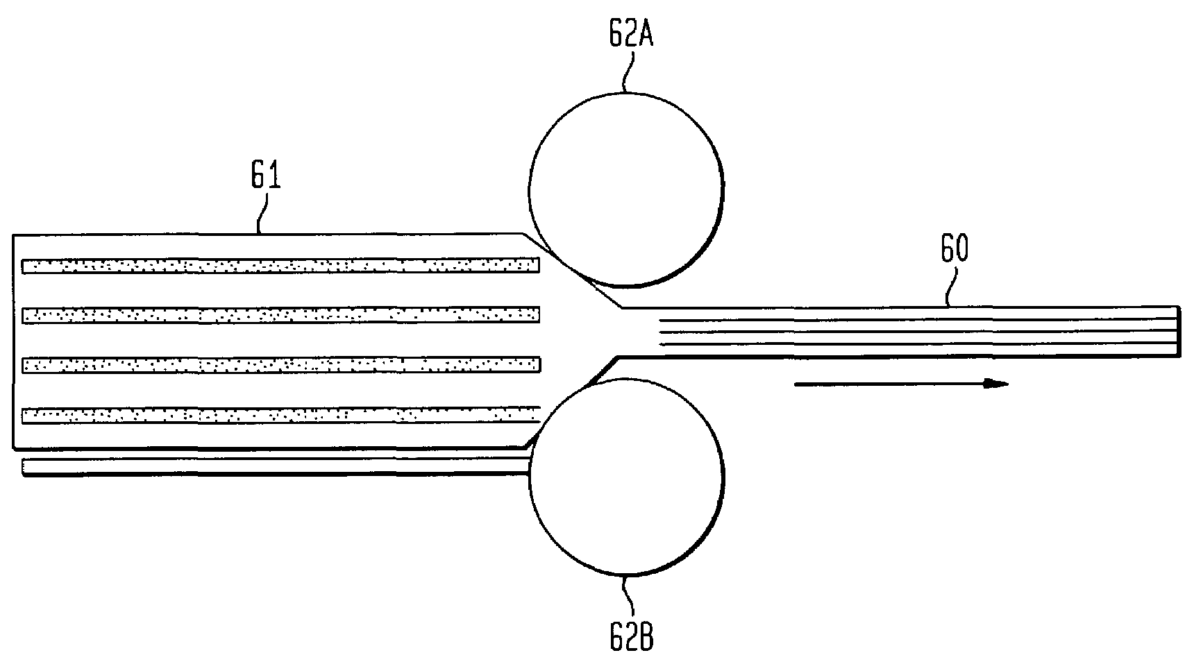
[0064]Reactive foils of Al and Ni are formed by cold rolling many 5 μm sheets of Ni and Al that are stacked together. FIG. 6 schematically illustrates fabrication of the foil 60 by passage of the stack 61 between rollers 62A and 62B. The sheets can be cold-rolled several times until the layers are reduced to the desired thickness.

example 2

[0065]Instead of utilizing foils comprised of multilayers of uniform thickness, a composite foil is used, in which nanolaminate reactive multilayers are deposited onto reactive microlaminate foils. As illustrated in FIG. 7 certain sections of layers 70 within the reactive foil 71 will be of a nanoscale (nanolaminate), while other sections 72 will be of micron-thick layers (microlaminate). The nanolaminate, as described above, will react easily and the reaction, once started, will self-propagate along the length of the foil without being quenched by the melting of the surrounding braze layers or bulk components. Thus, the nanolaminate can be viewed as an igniter for the microlaminate. The section 72 with microscale layers may not be able to sustain a self-propagating reaction at room temperature, but when heated by adjacent nanolaminate sections 70, it will sustain such a reaction. The foil can comprise alternate layers of Al and Ni.

example 3

[0066]In fabricating these composite foils, sheets of Al and Ni are rolled to form the microlaminate section and then a nanolaminate foil is vapor deposited onto either side of this microlaminate structure. Fabrication may also be performed through vapor deposition of the full composite with the microlaminate layers deposited at much higher rates without igniting the foil or causing unacceptable intermixing between the alternating layers during deposition.


PUM

PropertyMeasurementUnit
Thicknessaaaaaaaaaa
Force constantaaaaaaaaaa
Thicknessaaaaaaaaaa

Abstract

Reactive foils and their uses are provided as localized heat sources useful, for example, in ignition, joining and propulsion. An improved reactive foil is preferably a freestanding multilayered foil structure made up of alternating layers selected from materials that will react with one another in an exothermic and self-propagating reaction. Upon reacting, this foil supplies highly localized heat energy that may be applied, for example, to joining layers, or directly to bulk materials that are to be joined. This foil heat-source allows rapid bonding to occur at room temperature in virtually any environment (e.g., air, vacuum, water, etc.). If a joining material is used, the foil reaction will supply enough heat to melt or soften the joining material, which upon cooling will form a strong bond, joining two or more bulk materials. If no joining material is used, the foil reaction supplies heat directly to at least two bulk materials, melting or softening a portion of each bulk, which upon cooling, form a strong bond. Additionally, the foil may be designed with openings that allow extrusion of the joining (or bulk) material through the foil to enhance bonding.

Description

CROSS REFERENCE TO RELATED APPLICATIONS[0001]This application is a continuation-in-part of three U.S. patent applications (hereinafter “the parent applications”): 1) U.S. application Ser. No. 09 / 846,486 filed by T. P. Weihs et al. on May 1, 2001 now U.S. Pat. No. 6,736,942 and entitled “Freestanding Reactive Multilayer Foils”; 2) U.S. application Ser. No. 09 / 846,422 filed by T. P. Weihs et al. on May 1, 2001 now abandoned and entitled “Reactive Multilayer Structures For Ease of Processing and Enhanced Ductility”; and 3) U.S. application Ser. No. 09 / 846,447 filed by T. P. Weihs et al. on May 1, 2001 now U.S. Pat. No. 6,534,194 and entitled “Method of Making Reactive Multilayer Foil and Resulting Product.” Each of the three parent applications claims the benefit of U.S. Provisional Application Ser. No. 60 / 201,292 filed by T. P. Weihs et al. on May 2, 2000 and entitled “Reactive Multilayer Foils.” The three parent applications and the '292 provisional application are incorporated herei...

Claims


Application Information

Patent Timeline
IPC IPC(8): B32B15/00B23K20/08B23K1/00B23K20/00B23K20/06B23K28/00B23K35/02B23K35/34B32B15/01C06B21/00C06B45/14C23C14/14F24V30/00H05K3/34
CPCB23K1/0006B23K20/06B23K20/08B23K20/165B23K28/00B23K35/0238B23K35/34B32B15/01B32B15/017C06B21/0083C06B45/14C23C14/14F24J1/00H05K3/3494B23K20/00Y10T428/12944B23K35/0233C21D2211/008H05K3/3463H05K2203/0405H05K2203/1163Y10S228/902Y10S428/94Y10T428/12361Y10T428/12819Y10T29/302Y10T29/49826Y10T428/1275Y10T428/12632Y10T428/12903Y10T428/12028Y10T428/12438Y10T428/12069Y10T428/12076Y10T428/12451Y10T29/301Y10T428/1209Y10T428/12493Y10T29/308Y10T428/12063Y10T428/12229Y10T428/1259F24V30/00
Inventor WEIHS, TIMOTHY P.REISS, MICHAELKNIO, OMARSWISTON, JR., ALBERT JOSEPHVAN HEERDEN, DAVIDHUFNAGEL, TODD
Owner THE JOHN HOPKINS UNIV SCHOOL OF MEDICINE
Why Eureka
Try Eureka