Quantum well thermoelectric power source

Inactive Publication Date: 2006-09-21
HI Z TECH
View PDF4 Cites 37 Cited by
  • Summary
  • Abstract
  • Description
  • Claims
  • Application Information

AI Technical Summary

Benefits of technology

[0008] The present invention provides a quantum well thermoelectric module providing very high conversion of heat energy in to electrical energy. In prefered embodiments the module provides electric power for monitoring, measuring or detecting any of a variety of things (such as temperature, smoke, other pollution, flow, fluid level and vibration) and a transmitter for transmitting information measured or detected. In a preferred embodiment wireless monitor systems are utilized to monitor conditions at various locations aboard a ship and to wirelessly transmit information about those conditions to a central location. Preferably, a finned unit is provided to efficiently transfer heat from a module surface to the environment. A preferred quantum well choice is p type B9C / B4C and n-type Si / SiGe legs. Another preferred choice is n-doped Si / SiGe for the n-legs and p-doped Si / SiGe for the p-legs. At higher temperatures the preferred quantum well legs are alternating layers of silicon and silicon carbide for the n-legs and for the p-legs alternating layers of different stoichiometric forms of B-C.

Problems solved by technology

Workers in the thermoelectric industry have been attempting too improve performance of thermoelectric devices for the past 20-30 years with not much success.
Many locations do not have sunlight and in many locations bringing in power from the power company can be very expensive.
Many monitors with transmitters require very small amounts of power.

Method used


Image

  • Quantum well thermoelectric power source
  • Quantum well thermoelectric power source
  • Quantum well thermoelectric power source

Examples


first preferred embodiment

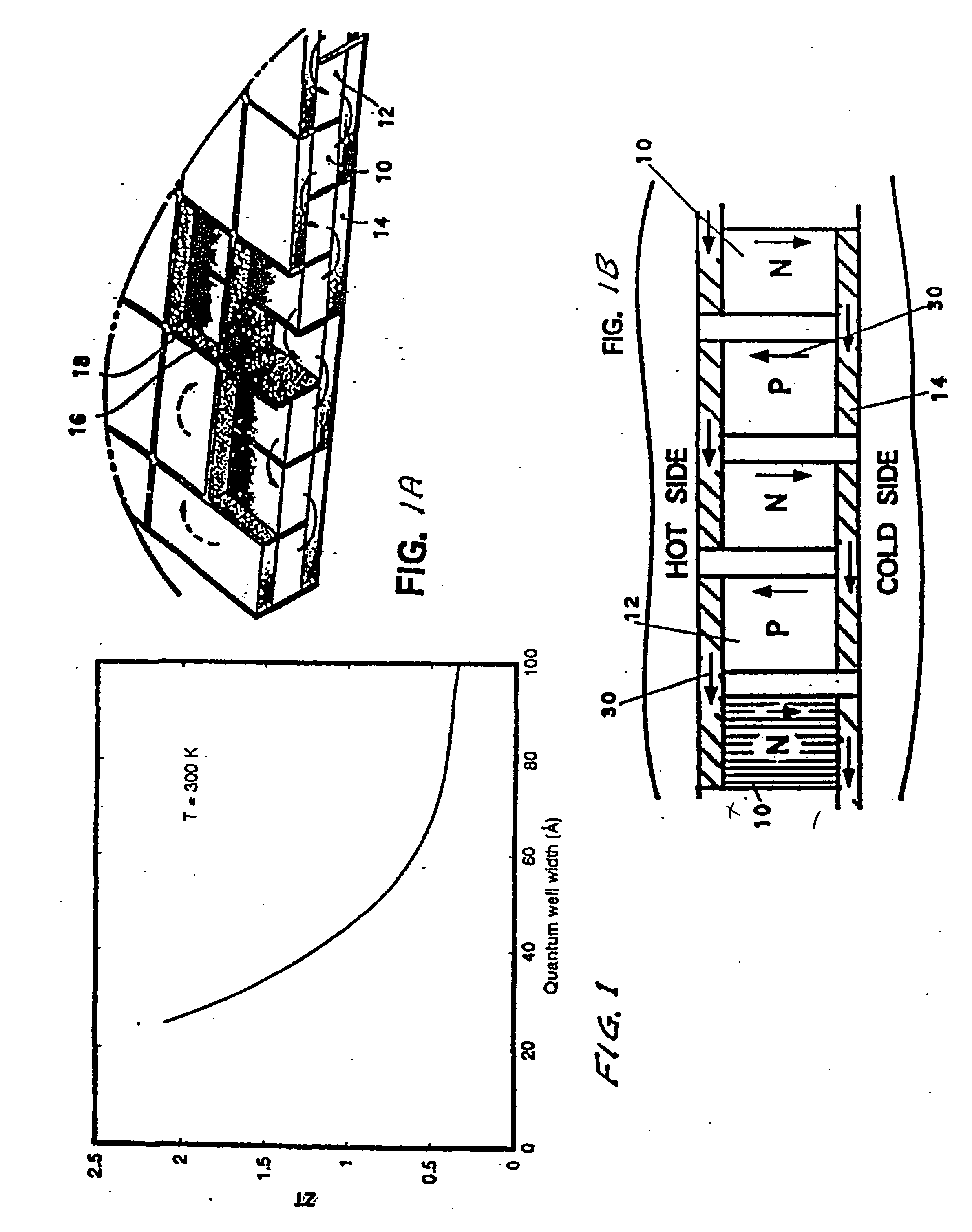
[0060] As explained above power generating capability of thin-film quantum well (QW) thermoelectric generators has been demonstrated in recent tests by Applicants where a high overall efficiency of 14% was measured. Higher efficiencies of 25% and 30% are theoretically possible with thicker QW films.

[0061] The thermal environment selected for the design of a first preferred embodiment corresponds is the compressor section of an Allison 501-K34 gas turbine, as shown in FIG. 11. In addition to its good potential for power harvesting, this equipment surface was selected because of the availability of complete temperature data (both the equipment surface temperature and the adjacent ambient air temperature) so that no assumptions would be necessary in the design analysis. The surface temperatures at locations No. 2, 3, or 4 of FIG. 11 are 111.2° C., 221.1° C., and 342.2° C. These surface temperatures, in conjunction with the maximum ambient air temperature of 71° C. in this area, will p...


PUM


Abstract

A quantum well thermoelectric module providing very high conversion of heat energy in to electrical energy. In prefered embodiments the module provides electric power for monitoring, measuring or detecting any of a variety of things (such as temperature, smoke, other pollution, flow, fluid level and vibration) and a transmitter for transmitting information measured or detected. In a preferred embodiment wireless monitor systems are utilized to monitor conditions at various locations aboard a ship and to wirelessly transmit information about those conditions to a central location. Preferably, a finned unit is provided to efficiently transfer heat from a module surface to the environment. A preferred quantum well choice is p type B9C / B4C and n-type Si / SiGe legs. Another preferred choice is n-doped Si / SiGe for the n-legs and p-doped Si / SiGe for the p-legs. At higher temperatures the preferred quantum well legs are alternating layers of silicon and silicon carbide for the n-legs and for the p-legs alternating layers of different stoichiometric forms of B-C.

Description

[0001] This application is a continuation in part of Ser. No. 10 / 734,336 filed Dec. 12, 2003, and Ser. No. 10 / 021,097 filed Dec. 12, 2001 which is incorporated herein by reference and also claims the benefit of Provisional Application Ser. No. 60 / 632639 filed Dec. 2, 2004. The present invention relates to thermoelectric devices and in particular techniques for producing electric power from existing heat sources and to very thin lattice thermoelectric devices. This invention was made in the course of or under Contract Number N00178-03-C-3018 with the US Naval Surface Warfare Center and the US Government has rights under any patent resulting from this application.BACKGROUND OF THE INVENTION [0002] A well-known use for thermoelectric devices is for the extraction of electric power from waste heat. For example, U.S. Pat. No. 6,527,548 discloses a self powered space heater for a truck in which heat energy for the heater is used to power electric components of the heater plus charge a bat...

Claims


Application Information

Patent Timeline
IPC IPC(8): F03B13/00
CPCG01K2215/00H01L35/22H01L35/30H01L35/32Y02T10/166Y02T10/12H10N10/855H10N10/13H10N10/17
Inventor JOVANOVIC, VELIMIRBASS, JOHN C.GHAMATY, SAEID
Owner HI Z TECH
Why Eureka
Try Eureka