Index device of machine tool and method of manufacturing same

Active Publication Date: 2014-01-30
FANUC LTD
View PDF8 Cites 1 Cited by
  • Summary
  • Abstract
  • Description
  • Claims
  • Application Information

AI Technical Summary

Benefits of technology

[0016]With the above configuration, the present invention provides for an index device of a machine tool and a method of manufacturing the index device of a machine tool that are capable of efficientl

Problems solved by technology

Since the gap space is filled with the air, the thermal conductivity is lower, which could cause heat generated during the operation of the motor to be retained within the motor, accelerating rise in temperature of the motor.
The motor becomes susceptible to overheat due to acceleration of temperature rise of the motor, which may d

Method used


Image

  • Index device of machine tool and method of manufacturing same
  • Index device of machine tool and method of manufacturing same
  • Index device of machine tool and method of manufacturing same

Examples


Example

First Embodiment

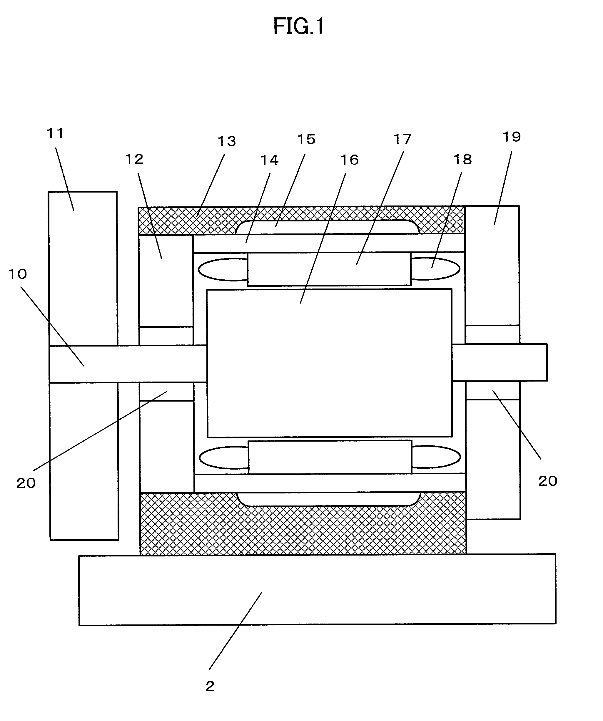
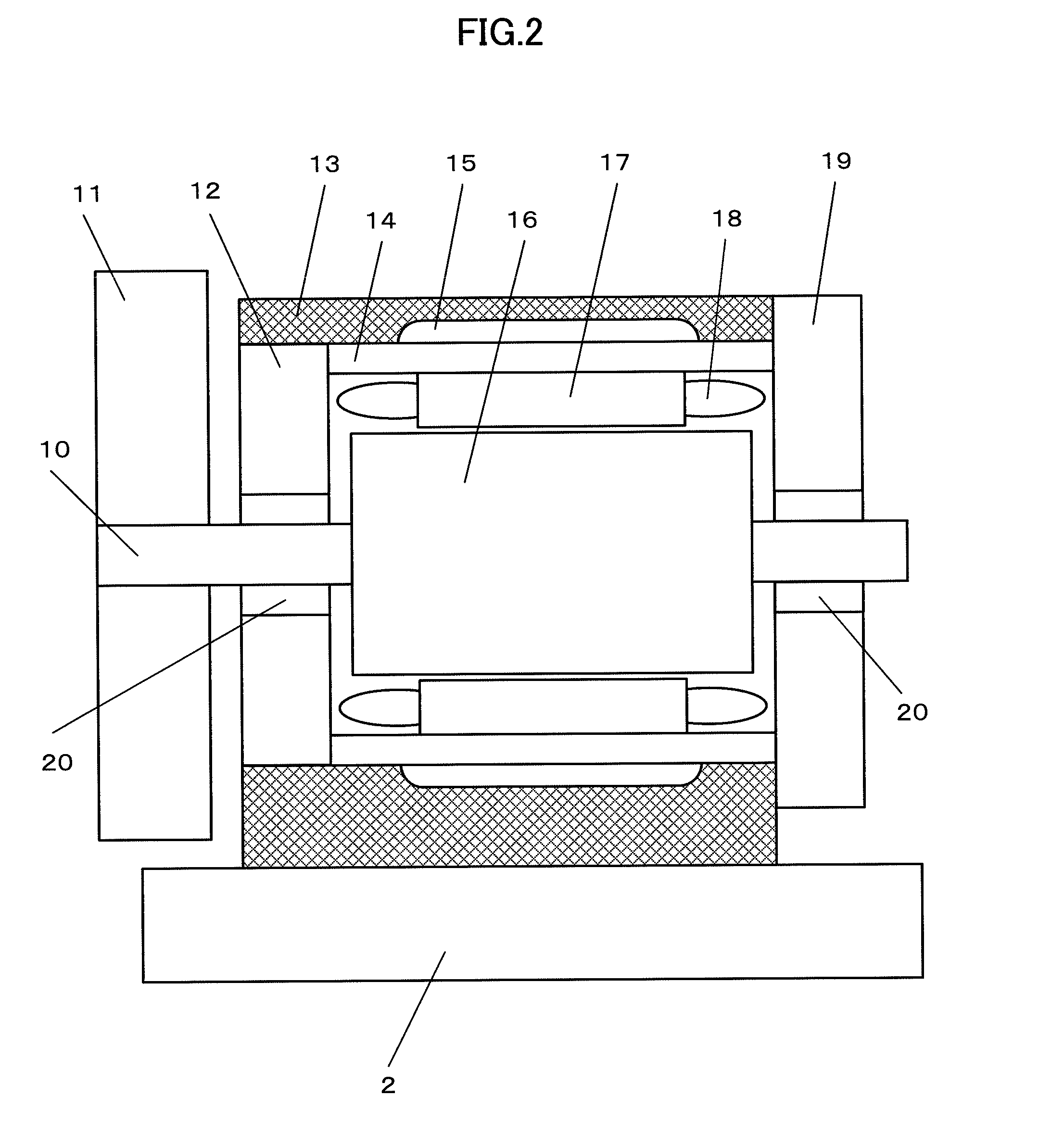
[0028]FIG. 2 is an explanatory diagram of an example in which a highly thermally conductive material is filled in gap between the outer periphery of a motor and the inner periphery of a motor housing casing. The structure of the index device having the motor built therein has been described in the background section, and thus the description thereof is not redundantly given.

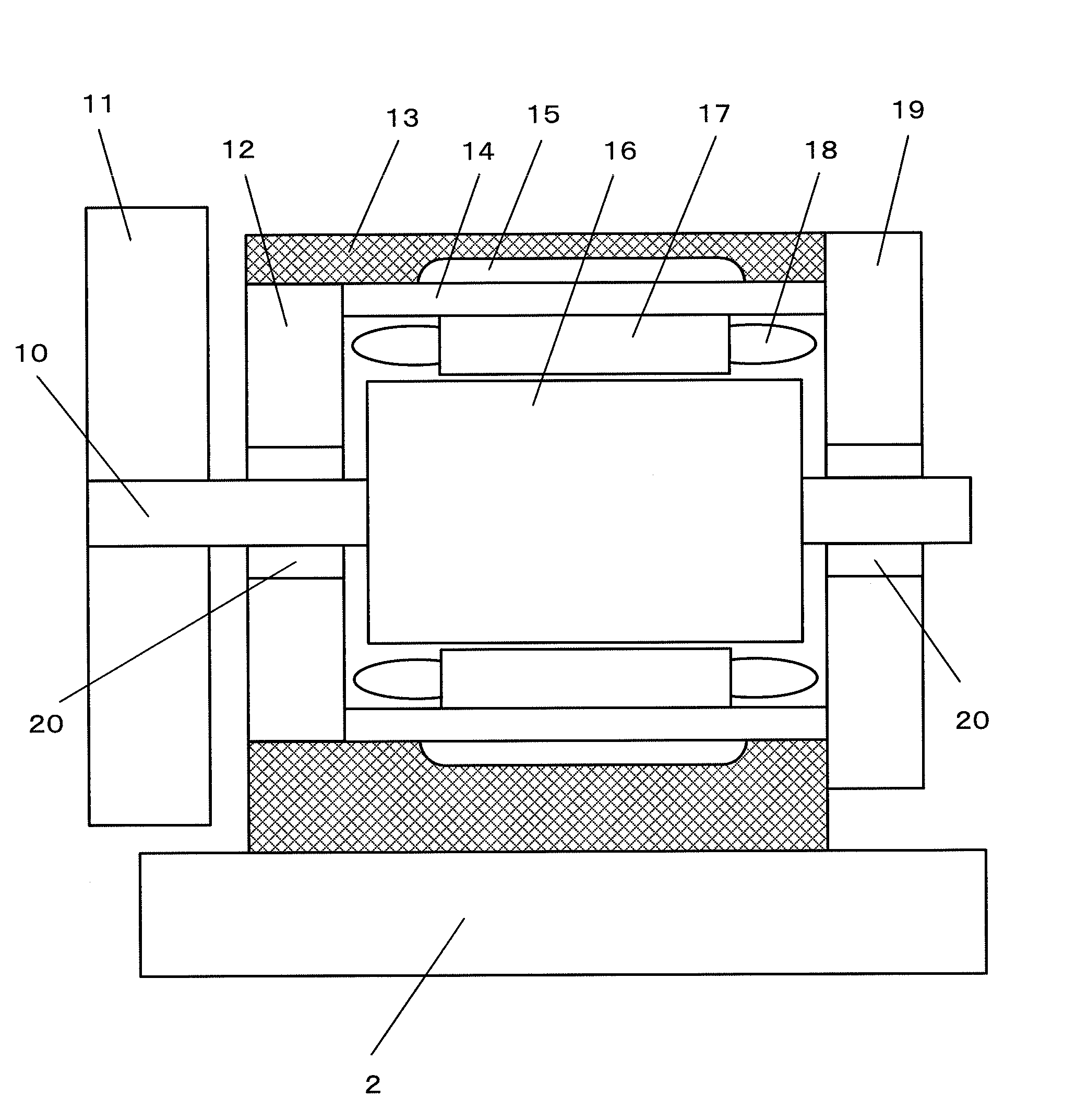
[0029]Description is given here of a configuration for an index device having a motor M built therein of a machine tool, to suppress temperature rise of the motor M. A material with higher thermal conductivity than the air is filled in gap space 15 created between a motor housing casing 13 and a case 14 of the motor. The gap space 15 is produced by the shape of the motor housing casing 13.

[0030]Materials with higher thermal conductivity than the air include, for example, gas such as nitrogen, liquid such as water, resin, solids such as metal, ceramic, glass, and carbon, and powder or liquid contai...

Example

Second Embodiment

[0031]FIG. 3 is an explanatory diagram of an example in which a sealing member is used to prevent a material filled in gap space that is created between a motor housing casing and a case of the motor from leaking from the gap space.

[0032]Providing gap for assembling a motor facilitates work of attaching a motor M to a motor housing casing 13. A sealing feature 21 such as an O ring or an oil seal is provided to prevent a material filled in gap space 15 that is created between the motor housing casing 13 and a case 14 of the motor, which material is higher in thermal conductivity than the air, from leaking from the gap space 15.

[0033]According to this embodiment, leakage of the highly thermally conductive material filled is preventable in filling gap between the outer periphery of the case 14 of the motor and the casing 13 for housing the motor of the index device with the material that is higher in thermal conductivity than the air. Further, in the case where the fil...

Example

Third Embodiment

[0034]FIG. 4 is an explanatory diagram of an example in which an opening for introducing and sealing a filling material is provided in a motor housing casing.

[0035]An opening is provided in such a way as to pass through a motor housing casing 13 from the outer peripheral surface thereof to gap space 15 created between the casing 13 and a case 14 of the motor, so as to conduct introduction and sealing of a material with higher thermal conductivity than the air. The opening for introducing and sealing in the gap space 15 the material with higher thermal activity than the air permits the material to be filled in the gap space 15. The function of the opening is enhanced by providing a plurality of such openings in the motor housing casing 13.

[0036]A pair of openings 22 and 23 is provided at an upper portion of the motor housing casing 13. A first opening 22 is used for pouring the highly thermally conductive material, and a second opening 23 is used for removing the air ...


PUM

PropertyMeasurementUnit
Diameteraaaaaaaaaa
Thermal conductivityaaaaaaaaaa

Abstract

An index device of a machine tool is driven by a motor. Gap space created between the outer periphery of the motor and the inner periphery of a casing for housing the motor is filled with a material that is higher in thermal conductivity than the air. With this configuration, heat to be generated during operation of the motor of the index device is efficiently transferrable to the motor housing casing.

Description

BACKGROUND OF THE INVENTION[0001]1. Field of the Invention[0002]The present invention relates to an index device of a machine tool having a motor built therein and a method of manufacturing the same.[0003]2. Description of the Related Art[0004]Recent machine tools such as machining centers use rotating table type index devices including a so-called direct drive structure in which a drive motor is directly coupled to the rotating shaft (see, for example, Japanese Patent Application Laid-Open No. 2009-248242). A direct drive index device is described with reference to FIG. 1.[0005]A rotating table 11 for placing a workpiece (not shown) thereon is attached to a shaft 10 of a motor M that is contained in a casing 13 for housing the motor of an index device. The motor M includes a stator 17 and a rotor 16. The stator 17 has a stator coil 18 wound around a case 14 of the motor at the inner peripheral side thereof. The rotor 16 is attached to the shaft 10 that is rotatably journaled at the...

Claims


Application Information

Patent Timeline
IPC IPC(8): H02K5/04H02K15/14
CPCH02K15/14H02K5/04H02K9/00Y10T29/49009H02K9/223H02K5/203
Inventor MUROTA, MASAHIRO
Owner FANUC LTD
Why Eureka
Try Eureka