Energy converters utilizing fluid-induced oscillations

Inactive Publication Date: 2009-12-03
HUMDINGER WIND ENERGY
View PDF40 Cites 43 Cited by
  • Summary
  • Abstract
  • Description
  • Claims
  • Application Information

AI Technical Summary

Benefits of technology

[0008]This electric generator operates at a variety of wind speeds, including lower speeds than required for most turbine-based generators. Moreover, the cost of an exemplary generator of this disclosure is substantially lower than most other fluid

Problems solved by technology

Moreover, the cost of an exemplary generator of this disclosure is s

Method used


Image

  • Energy converters utilizing fluid-induced oscillations
  • Energy converters utilizing fluid-induced oscillations
  • Energy converters utilizing fluid-induced oscillations

Examples


Example

[0031]In the following description, for the purposes of explanation, numerous specific details are set forth in order to provide a thorough understanding of the present disclosure. It will be apparent, however, to one skilled in the art that the present disclosure may be practiced without these specific details. In other instances, well known structures and devices are shown in block diagram form in order to avoid unnecessarily obscuring this disclosure.

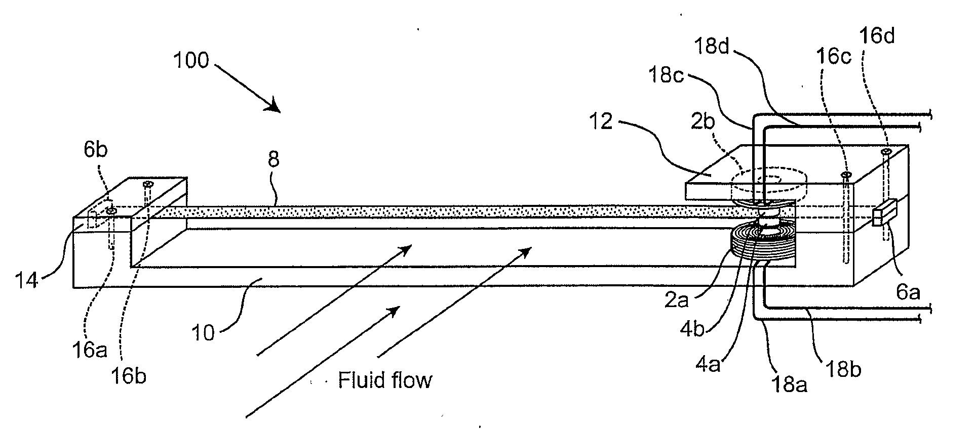
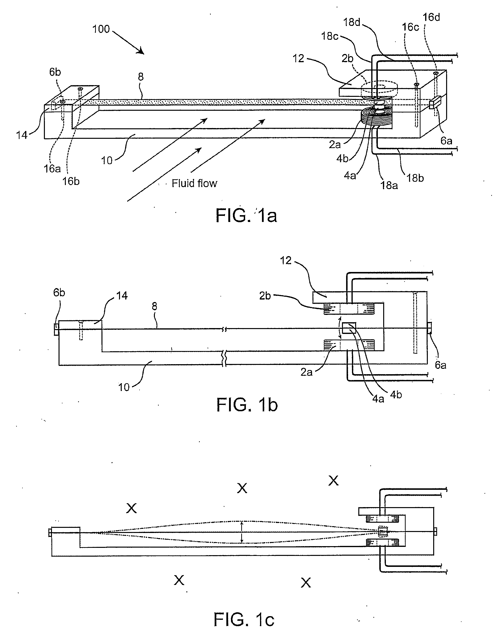
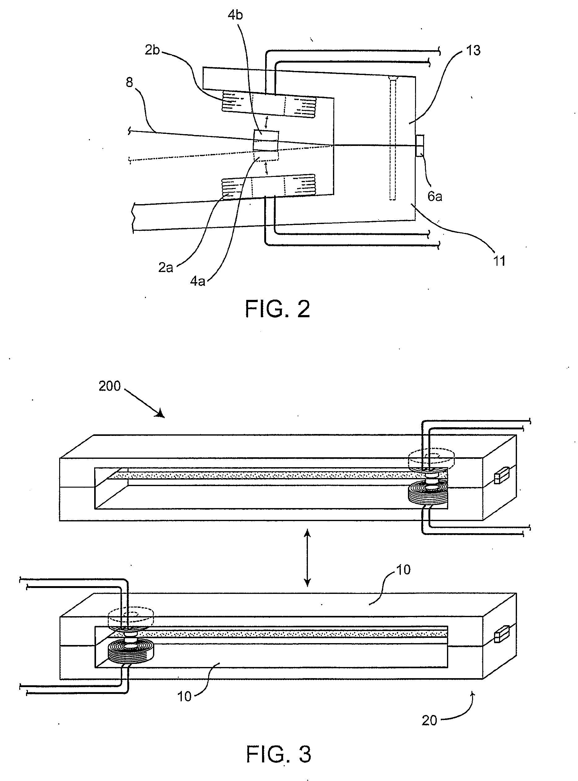
[0032]FIG. 1a depicts an exemplary generator 100 according to this disclosure. The generator 100 includes a supporting structure and an elongated membrane 8. The supporting structure comprises a supporting base 10 and two supporting structure clamps 12 and 14.

[0033]The membrane 8 is made from a flexible material, such as ripstock nylon, super thin polyester film, mylar-coated taffeta, Kevlar tapes, or polyethylene film, etc. The membrane 8 has two main surfaces on opposite sides and two thin edges. In this disclosure, a surface plane...


PUM


Abstract

An energy converter for inducing membrane vibrations when subject to a fluid flow and converting the kinetic energy embedded in the fluid flow into another form of energy, such as electricity. The energy converter includes a supporting structure and multiple generator units. Each generator unit includes at least one flexible membrane, and at least one electrical conductor and at least one magnetic field generator configured to apply a magnetic field to the at least one electrical conductor, wherein one of the electrical conductor and the magnetic field generator is attached to the membrane and configured to move with the membrane. Each membrane vibrates when subject to the fluid flow and has at least two ends supported by the supporting structure. The vibration of each membrane creates a relative movement between the conductor and a magnetic field generated by the magnetic field generator, which induces a current. A power conditioning circuit is provided to condition the current.

Description

RELATED APPLICATIONS[0001]This application relates to co-pending U.S. patent application Ser. No. 11 / 566,127, filed Dec. 1, 2006 and titled “GENERATOR UTILIZING FLUID-INDUCED OSCILLATIONS,” and to U.S. patent application Ser. No. ______ (Attorney Docket No. 080387-0014), entitled “FLUID-INDUCED ENERGY CONVERTER WITH CURVED PARTS,” and filed concurrently herewith; and claims the benefits of priority from U.S. Provisional Patent Application No. 60 / 932,304, filed May 30, 2007, entitled “GENERATOR UTILIZING FLUID-INDUCED OSCILLATIONS,” and from U.S. Provisional Patent Application No. 60 / 950,227, filed Jul. 17, 2007 and entitled “GENERATOR AND CIRCUIT UTILIZING FLUID-INDUCED OSCILLATIONS,” the disclosures of which are incorporated herein by reference in their entireties.FIELD OF DISCLOSURE[0002]This application generally relates to techniques of harvesting energy from flowing fluids, such as air, water, etc., and more specifically, to designs and structures of energy converters that conv...

Claims


Application Information

Patent Timeline
IPC IPC(8): F03B13/00
CPCF03B17/06F03D5/00F03D9/00Y02E10/72H02K35/02Y02E10/28Y02E10/70H02K7/1892Y02E10/30Y02E10/20
Inventor FRAYNE, SHAWN MICHAEL
Owner HUMDINGER WIND ENERGY
Why Eureka
Try Eureka