Heat-removing device and heat-removing method of vehicle interior part

a technology of heat removal device and vehicle interior, which is applied in the direction of indirect heat exchangers, heating types, lighting and heating apparatus, etc., can solve the problems of deteriorating the heat removal efficiency of the instrument panel, the inability to efficiently collect and conduct the entire instrument panel to the heat pipe, etc., to improve the moldability of the vehicle interior part, the effect of efficient transfer of the heat accumulated

Inactive Publication Date: 2006-06-29
NISSAN MOTOR CO LTD
View PDF5 Cites 0 Cited by
  • Summary
  • Abstract
  • Description
  • Claims
  • Application Information

AI Technical Summary

Benefits of technology

[0007] The present invention is made in the light of the problem. An object of the present invention is to provide a heat-removing device and a heat-removing method for a vehicle interior part exposed to the direct sunlight, capable of efficiently transferring the heat accumulated on the vehicle interior part to a heat pipe, thus improving the heat-removing efficiency of the vehicle interior part.
[0008] Another object of the present invention is to provide a heat-removing device and a heat-removing method for a vehicle interior part exposed to the direct sunlight, capable of improving moldability of the vehicle interior part.

Problems solved by technology

However, in the aforementioned device, since the heat pipe is merely embedded in the inner side of the instrument panel, the heat of the entire instrument panel cannot be collected and conducted to the heat pipe efficiently, thus deteriorating the heat removing efficiency of the instrument panel.

Method used


Image

  • Heat-removing device and heat-removing method of vehicle interior part
  • Heat-removing device and heat-removing method of vehicle interior part
  • Heat-removing device and heat-removing method of vehicle interior part

Examples


first embodiment

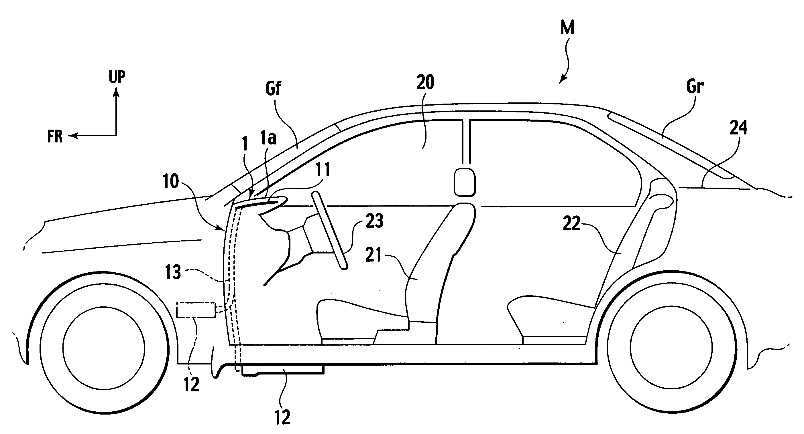
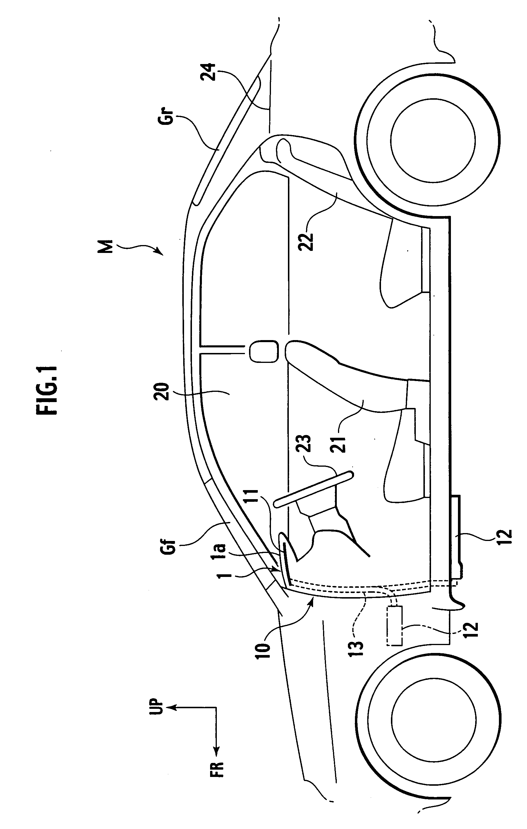
[0028] As shown in FIG. 1, an instrument panel 1 is an interior part located just below a windshield Gf of a vehicle M and exposed to direct sunlight. A vehicle heat-removing device 10 according to the embodiment is installed to the instrument panel 1, so as to restrain excessive increase in the temperature thereof when the vehicle M is left parked in a place subject to direct sunlight for a certain period.

[0029] In a vehicle passenger compartment 20, there are front seats 21 including a driver's seat and a passenger seat behind the instrument panel 1, and a rear seat 22 therebehind. At the driver's seat side of the front seats 21, there is a steering wheel 23 at a lower portion of the instrument panel 1.

[0030] A rear parcel shelf 24 as another vehicle interior part is provided directly below a rear windshield Gr in the rear of the vehicle passenger compartment 20.

[0031] The incident direct sunlight through the windshield Gf is irradiated onto the surface of a top board (or a das...

second embodiment

[0059]FIG. 6 represents a second embodiment of the invention in which the same components as those of the first embodiment are designated as the same reference numerals. The description of those components, thus, will be omitted.

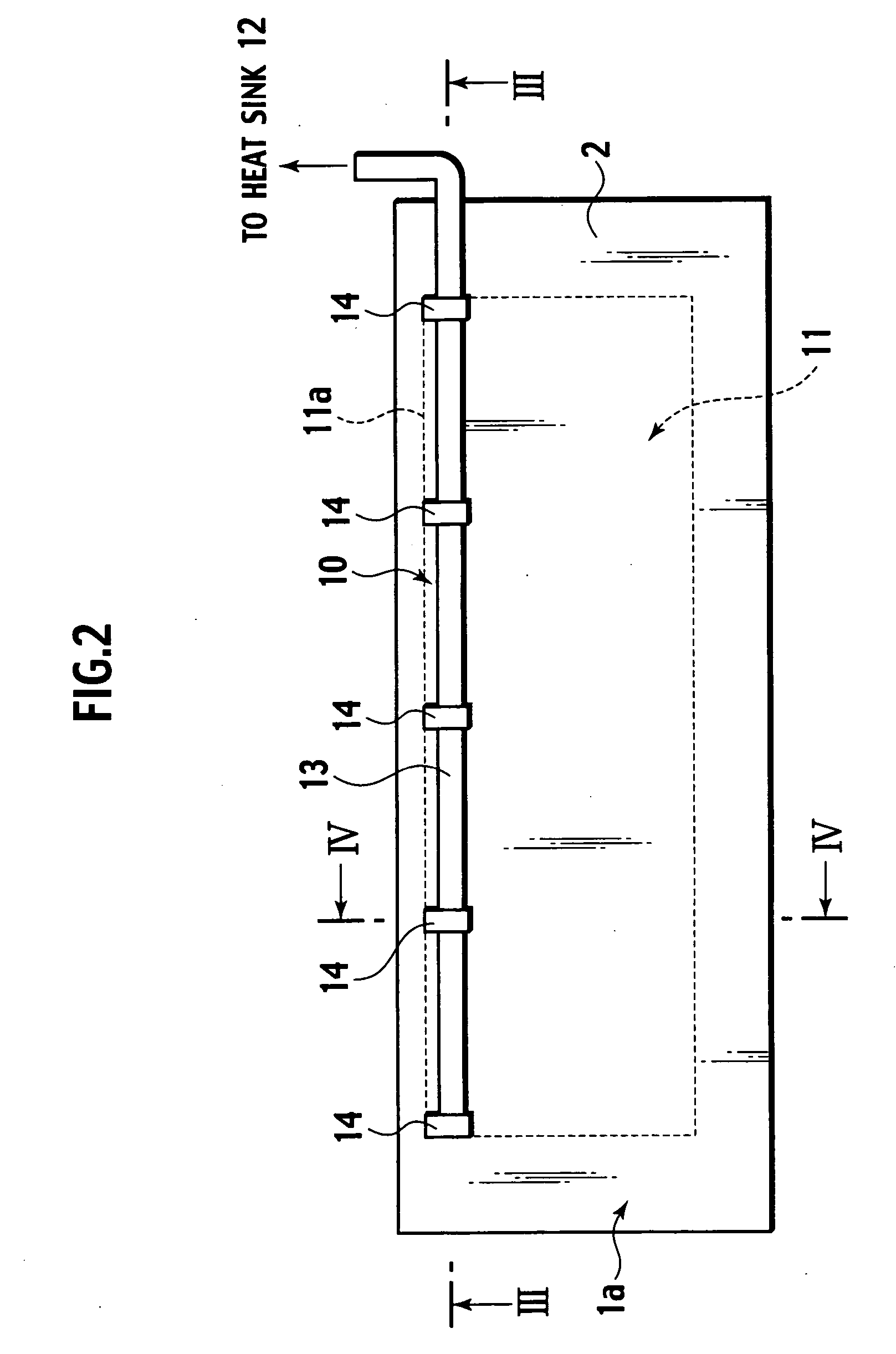
[0060] Basically a vehicle heat-removing device 10A has substantially the same structure as that of the first embodiment, and is provided with a heat conducting plate 11 for collecting the heat accumulated on a skin material 3, and a heat pipe 13 provided on an inner side of an inner surface 2a of a baseboard 2 and connected in heat-conductive relationship to the heat conducting plate 11 so as to transfer the heat of the skin material 3 collected by the heat conducting plate 11 to a heat sink 12 (see FIG. 1).

[0061] In the second embodiment, the baseboard 2 is formed of an upper portion and a lower portion, that is, an outer baseboard 2b and an inner baseboard 2c, respectively. The heat conducting plate 11 is insert-molded into the inner surface of the oute...

third embodiment

[0065]FIG. 7 represents a third embodiment of the present invention in which the same components as those of the first and the second embodiments are designated as the same reference numerals. The description of those components, thus, will be omitted.

[0066] Basically a vehicle heat-removing device 10B has substantially the same structure as that of the first embodiment, and is provided with a heat conducting plate 11 for collecting the heat accumulated on a skin material 3, and a heat pipe 13 provided on an inner side of an inner surface 2a of a baseboard 2 and connected in heat-conductive relationship to the heat conducting plate 11 so as to transfer the heat of the skin material 3 collected by the heat conducting plate 11 to a heat sink 12 (see FIG. 1).

[0067] In this embodiment, the skin material 3 is formed of a skin surface material 3a and a soft pad 3b on the inner side thereof. The soft pad 3b is formed of open-cell foam of polyethylene foam, polyurethane foam and the like....


PUM


Abstract

A heat-removing device for a vehicle including: an interior part having a plate portion exposed to direct sunlight including a baseboard formed of a resin or a composite material containing a resin and a skin material which covers an outer surface of the baseboard; a heat conducting plate for collecting heat from the skin material, provided on an inner side of the skin material of the plate portion and inside of an inner surface of the baseboard in a direction of a thickness of the baseboard; and a heat pipe provided on an inner side of the inner surface of the baseboard and connected in heat-conductive relationship to the heat conducting plate, which transfers heat collected by the heat conducting plate to a heat releasing device.

Description

BACKGROUND OF THE INVENTION [0001] 1. Field of Invention [0002] The present invention relates to a heat-removing device and a heat-removing method to remove heat from a vehicle interior part to the outside. [0003] 2. Description of Related Art [0004] When a vehicle is left parked in a place subject to direct sunlight for a certain period of time, temperature of a vehicle interior part will become considerably high. Under such circumstance, temperature of an upper surface of an instrument panel disposed directly below the windshield may exceed 90 degree centigrade [° C.]. The heat accumulated on the instrument panel tends to be radiated into the air in a vehicle passenger compartment, which is considered as one of main reasons to increase the temperature of the vehicle passenger compartment. [0005] Japanese Patent Application Laid-Open Publication No. 2004-58943 discloses a device for removing heat accumulated on an instrument panel using a heat pipe connected to a vehicle body and a...

Claims


Application Information

Patent Timeline
Patent Type & Authority Applications(United States)
IPC IPC(8): F24H9/06F24D19/04F24D19/06
CPCB60H1/00271B60H1/0055B60H1/00295B60H2001/00307
Inventor NAGAYAMA, HIROKIKATO, HAJIMEISHIKAWA, TERUAKI
Owner NISSAN MOTOR CO LTD
Why Eureka
Try Eureka