Structure of cooling tower

a technology of cooling tower and structure, which is applied in the direction of carburetor air, lighting and heating equipment, separation processes, etc., can solve the problems of power shortage, reduced dissipation capability of cooling tower b>1/b>, and limited roof space, so as to increase the efficiency of water chiller

Inactive Publication Date: 2009-12-31
NAT TAIPEI UNIV OF TECH
View PDF15 Cites 2 Cited by
  • Summary
  • Abstract
  • Description
  • Claims
  • Application Information

AI Technical Summary

Benefits of technology

[0008]The primary aspect of this invention is to provide an improved structure of cooling tower that can avoid the short circulation of the warm and wet air refluxing into the cooling tower, by means of induction openings and a diffuser stack, so as to increase the efficiency of the water chiller.
[0009]Another aspect of this invention is to provide an improved structure of cooling tower that can increase the heat removal efficiency of the cooling tower and the energy efficiency of the associated water chiller, so as to decrease the power consumption.
[0010]In addition, a further aspect of this invention is to provide an improved structure of cooling tower that applies a diffuser stack disposed at one end surface of a fan housing to effectively increase the flow rate of the outlet air from the fan housing as well as to facilitate the induction of air through induction openings.
[0011]An improved structure of cooling tower that can fulfill the above aspects that mainly comprises a cooling tower, a fan housing, more than one induction openings, and a diffuser stack. The fan housing contains a fan disposed therein. The induction openings are distributed on the fan housing and located below the fan, for inducing the warm and wet air outside the cooling tower into the cooling tower. The diffuser stack is disposed at one end surface of the fan housing to effectively increase the flow rate of the outlet air from the fan housing as well as to facilitate the induction of air through the induction openings. In operation, cold air is drawn into the cooling tower by the fan through inlet openings of the cooling tower so as to exchange heat with the condensing water within a water chiller, when the warm and wet air is drawn out of the cooling tower, the warm and wet air outside the cooling tower is induced in through the induction openings and then be drawn out so that circulation reflux of warm and wet air, which tends to occur in conventional cooling towers, can be avoided and therefore the efficiency of the water chiller is increased.

Problems solved by technology

Although the application of air conditioners brings healthy and comfortable surroundings for living, it often results in the crisis of power shortage in summer.
Moreover, due to the difficulty of establishing power plants and the global decrease in energy resources, a critical issue is how to save and utilize energy efficiently.
However, the available roof space is rather limited for accommodating multiple cooling towers connected in parallel.
This short circulation can impose heavier loads on the cooling tower 1; thus, the dissipation capability of the cooling tower 1 can be reduced significantly, which causes the temperature of the outlet condensing water to be too high.
As a result, the efficiency of the water chiller will be decreased and the power consumption will be increased.
Since the conventional way has such drawbacks as described above, it is hardly a good solution.

Method used


Image

  • Structure of cooling tower
  • Structure of cooling tower
  • Structure of cooling tower

Examples


Embodiment Construction

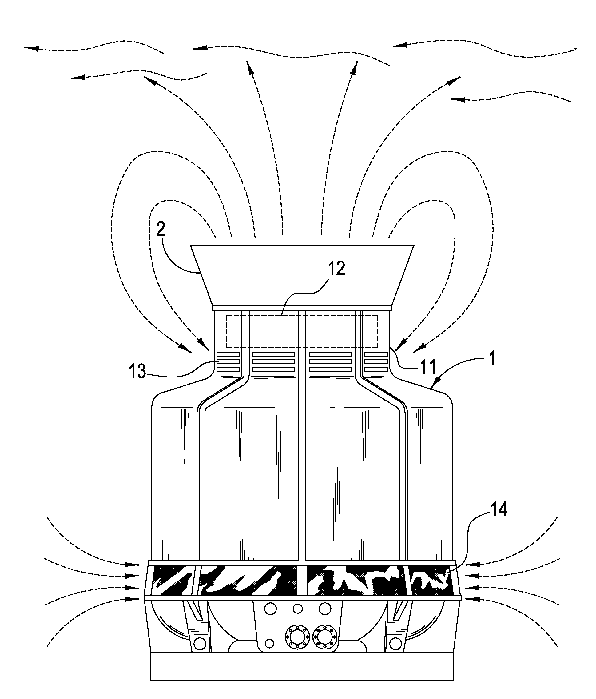
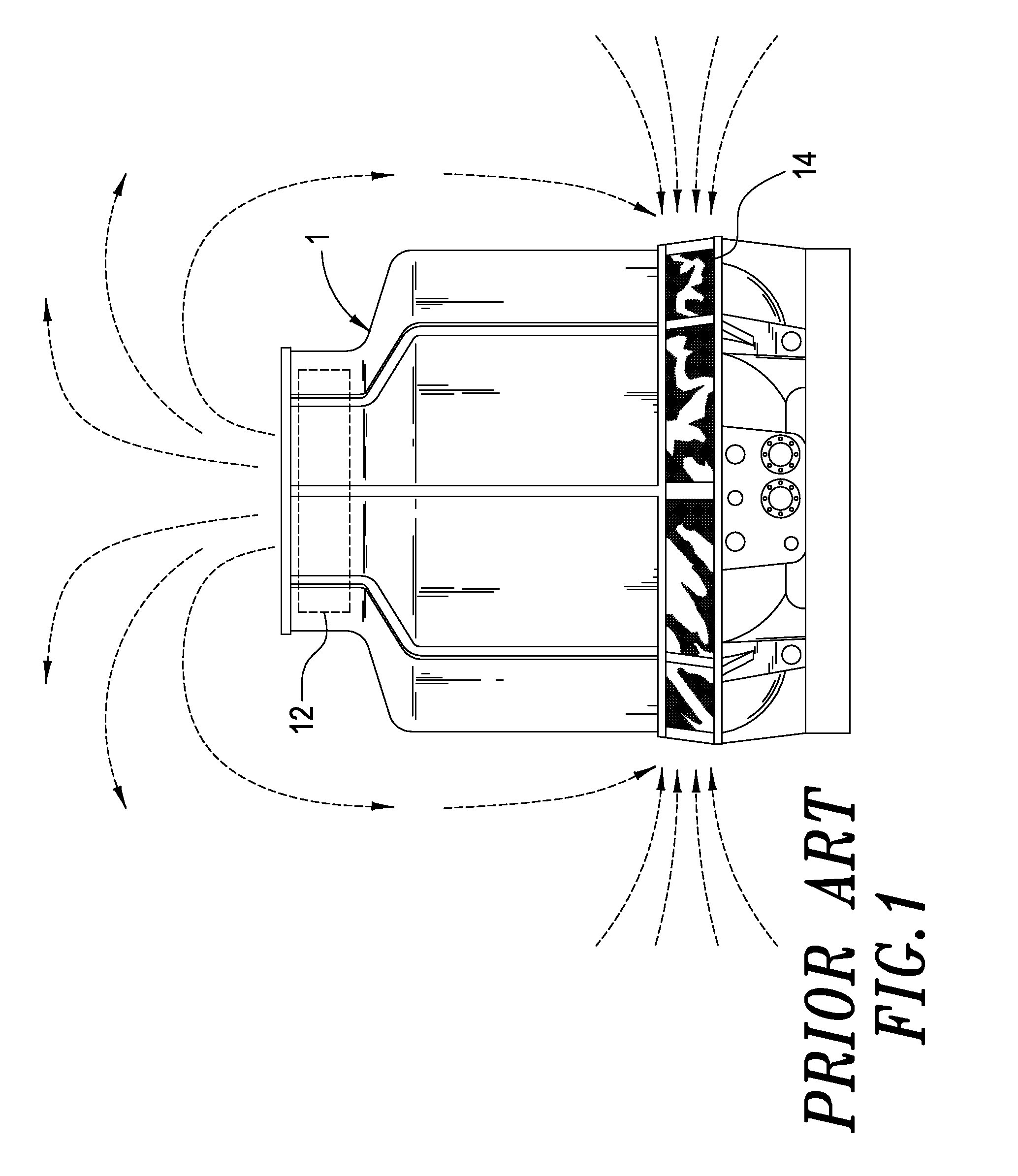
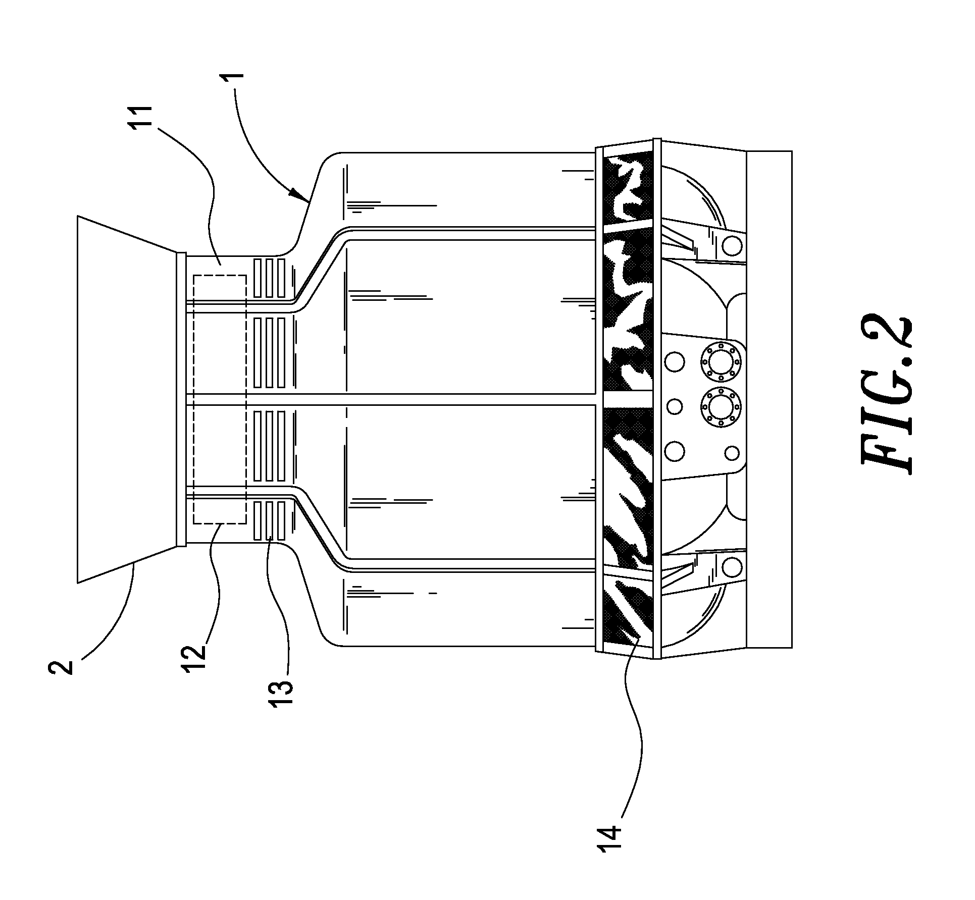
[0016]Referring to FIG. 2, which shows the improved structure of cooling tower according to the present invention, the structure of a cooling tower mainly comprises a cooling tower 1. The cooling tower 1 comprises a fan housing 11 formed at the upper portion thereof. The fan housing 11 contains a fan 12 disposed therein. The cooling tower 1 comprises more than one induction openings 13 distributed on the fan housing 11 and located below the fan 12. The cooling tower 1 also comprises more than one inlet openings 14 disposed at the lower portion thereof,

[0017]The cooling tower 1 comprises a diffuser stack 2 disposed at the end surface of the fan housing 11. The diffuser stack 2 is a chimney with a wide upper portion and a narrow lower portion.

[0018]The improved structure of cooling tower according to the present invention is composed of the elements described above. By means of the induction openings and the diffuser stack in cooperation, the capability of the fan to draw air is incre...


PUM

PropertyMeasurementUnit
structureaaaaaaaaaa
population densityaaaaaaaaaa
temperatureaaaaaaaaaa

Abstract

An improved structure of cooling tower includes a fan housing with a fan disposed therein, induction openings distributed on the fan housing and located below the fan, and a diffuser stack disposed at one end surface of the fan housing. In operation, cold air is drawn into the cooling tower by the fan through inlet openings of the cooling tower so as to exchange heat with the condensing water within a water chiller. When warm and wet air is drawn out of the cooling tower and the warm and wet air outside the cooling tower is induced in through the induction openings and then is drawn out, circulation reflux of warm and wet air, which tends to occur in conventional cooling towers, can be avoided and therefore increase the efficiency of the water chiller.

Description

BACKGROUND OF THE INVENTION[0001]1. Field of the Invention[0002]The present invention relates to an improved structure of cooling tower and, in particular, to an improved structure of cooling tower that can avoid short circulation of warm and wet air refluxing into the cooling tower, by means of induction openings and a diffuser stack, so that the water chiller increases its efficiency.[0003]2. Description of the Prior Art[0004]With developments in industry and commerce, people hold a heightened standard of living. Nowadays, air conditioners have been indispensable for residential or commercial buildings. Although the application of air conditioners brings healthy and comfortable surroundings for living, it often results in the crisis of power shortage in summer. Moreover, due to the difficulty of establishing power plants and the global decrease in energy resources, a critical issue is how to save and utilize energy efficiently.[0005]Generally, an air conditioning system operates b...

Claims


Application Information

Patent Timeline
Patent Type & Authority Applications(United States)
IPC IPC(8): B01F3/04
CPCF28F25/10Y10S261/11
Inventor CHUAH, YEW-KHOYLIU, CHIA-WEIYAO, NIEN-HUNGHUNG, MIN-HSIANG
Owner NAT TAIPEI UNIV OF TECH
Why Eureka
Try Eureka