
Evaporator, condenser and loop heat pipe

An evaporator and condenser technology, which is used in cooling/ventilation/heating renovation, indirect heat exchangers, lighting and heating equipment, etc., can solve the problem that heat pipe radiators and liquid cooling structures cannot meet the cooling needs of servers, and avoid The effect of heating up or even evaporating, improving the efficiency of heat efflux, and improving the efficiency of replenishment

Active Publication Date: 2022-03-25
北京微焓科技有限公司 +1
View PDF4 Cites 2 Cited by
  • Summary
  • Abstract
  • Description
  • Claims
  • Application Information

AI Technical Summary

Problems solved by technology

[0007] The purpose of this application is to provide an evaporator, radiator and loop heat pipe to solve the problem that the heat pipe radiator and liquid cooling structure in the prior art cannot meet the needs of servers and servers with high heat consumption. Technical issues with cooling requirements of equipment

Method used


Image

  • Evaporator, condenser and loop heat pipe
  • Evaporator, condenser and loop heat pipe
  • Evaporator, condenser and loop heat pipe

Examples


Embodiment 1

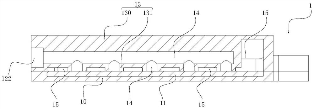
[0065] see figure 1 , figure 2 and see Figure 3 to Figure 11 As shown, the embodiment of the present application provides an evaporator 1 including a shell and a heat exchange evaporation layer 11 .

[0066] The inside of the housing is formed with a liquid replenishment chamber 14, an evaporation chamber 15 and an installation chamber. The housing is provided with a liquid inlet 122 communicating with the liquid replenishing chamber 14 and an air outlet 123 communicating with the evaporation chamber 15, wherein the heat transfer evaporation The layer 11 is arranged in the installation chamber, and the liquid replenishment chamber 14 and the evaporation chamber 15 are separated by the heat exchange evaporation layer 11 .

[0067] Among them, the evaporator 1 is used to be arranged on the heat source 4, and the temperature of the liquid working medium absorbs heat in the evaporator 1, and when the temperature reaches its boiling point, the phase changes into a high-temperat...

Embodiment 2

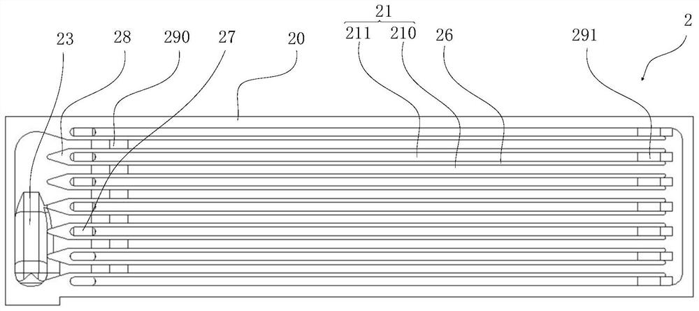
[0095] combine figure 1 , figure 2 , Figure 5 to Figure 11 and see image 3 and Figure 4 As shown, in the condenser 2 provided in this embodiment, a condensing chamber is formed inside the condensing body 20 , and the condensing body 20 is formed with a heat dissipation side wall 22 corresponding to the condensing chamber.

[0096] Optionally, the condensation body 20 includes a plate base 200 and a cover plate 201, the plate base 200 is provided with a groove, the cover plate 201 covers the groove, and the condensation cavity is formed by the groove.

[0097] The condensing body 20 is provided with an inlet passage 23 and an outlet passage 24, the inlet of the inlet passage 23 and the outlet of the outlet passage 24 penetrate the outer wall of the condensation body 20, and the outlet of the inlet passage 23 and the inlet of the outlet passage 24 are connected condensation cavity.

[0098] In order to enable the liquid working medium to flow out of the condensing body ...

Embodiment 3

[0111] Embodiment 3 provides a loop heat pipe 3, combined with Figure 1 to Figure 4 and see Figure 5 to Figure 11 As shown, this embodiment includes a radiator, the evaporator 1 in the first embodiment and the condenser 2 in the second embodiment, and the technical characteristics of the evaporator 1 disclosed in the first embodiment and the condenser 2 in the second embodiment are also Applicable to this embodiment, the technical features of the evaporator 1 disclosed in the first embodiment and the condenser 2 disclosed in the second embodiment will not be described repeatedly.

[0112] In the optional solution of this embodiment, the radiator is arranged on the heat dissipation side wall 22 of the condenser 2, so that the heat dissipation side wall 22 of the condenser 2 is cooled by the radiator, that is, the high temperature gas working medium inside the condenser 2 is cooled. Allow to cool.

[0113] Wherein, the radiator is an air-cooled radiator 30 or a liquid-cooled...


PUM


Abstract

The invention relates to the technical field of heat dissipation equipment, in particular to an evaporator, a condenser and a loop heat pipe. The evaporator comprises a shell and a heat exchange evaporation layer; a liquid supplementing cavity, an evaporation cavity and a mounting cavity are formed in the shell, and a liquid inlet communicated with the liquid supplementing cavity and an air outlet communicated with the evaporation cavity are formed in the shell; the heat exchange evaporation layer is arranged in the installation cavity, and the liquid supplementing cavity and the evaporation cavity are separated through the heat exchange evaporation layer. The condenser comprises a condensation body, a condensation cavity is formed in the condensation body, and the condensation body is provided with a heat dissipation side wall corresponding to the condensation cavity; the condensation body is provided with an air inlet channel and a liquid outlet channel, an inlet of the air inlet channel and an outlet of the liquid outlet channel penetrate through the outer wall of the condensation body, and an outlet of the air inlet channel and an inlet of the liquid outlet channel communicate with the condensation cavity. The loop heat pipe comprises the evaporator and a condenser. According to the evaporator, the condenser and the loop heat pipe, gas-liquid separation is achieved, the resistance for supplementing a liquid working medium into the liquid supplementing cavity is effectively reduced, and it is ensured that a heat source is continuously and stably cooled.

Description

technical field [0001] The present application relates to the technical field of heat dissipation equipment, in particular to an evaporator, a condenser and a loop heat pipe. Background technique [0002] Large-scale equipment such as servers or servers are usually installed in dedicated computer rooms, and are equipment with high heat consumption. Therefore, the heat dissipation requirements of the computer room increase with the increase in size and the power density of the internal cabinets. At present, the heat pipe technology plays an important role in the heat dissipation of equipment in the computer room. [0003] Wherein, one end of the heat pipe is installed at the heat-taking end, and the heat-taking end is arranged at the CPU / GPU of the server or the heat-generating chip of the server, and the other end of the heat pipe is installed at the heat-dissipating end, and the inner wall of the heat pipe is formed with a capillary core layer, thereby The cooling medium i...

Claims


Application Information

Patent Timeline
Patent Type & Authority Applications(China)
IPC IPC(8): H05K7/20F28D15/02F28D15/04
CPCH05K7/208H05K7/20309H05K7/20318H05K7/20336F28D15/0266F28D15/04
Inventor 李想刘新生张晓屿叶青松倪杨连红奎孙萌徐亮范春波杨宏辉
Owner 北京微焓科技有限公司
Learn More