Ultrathin soaking plate and manufacturing method thereof

A manufacturing method and vapor chamber technology, applied in the direction of indirect heat exchangers, lighting and heating equipment, etc., can solve the problems of difficulty in further reducing the thickness of vapor chamber, complicated manufacturing process, and complicated manufacturing process, and achieve low cost and increased Effect of increased surface area and heat transfer area

Active Publication Date: 2016-08-17
GUANGZHOU HUAZUAN ELECTRONICS TECH
View PDF8 Cites 26 Cited by
  • Summary
  • Abstract
  • Description
  • Claims
  • Application Information

AI Technical Summary

Problems solved by technology

[0005] However, both the inner surface of the cover and the bottom of the traditional vapor chamber require sintered copper powder porous structure, and at the same time, the central cavity should be reserved as a channel for vapor diffusion, in order to connect the cover and bottom, and to promote the return of liquid from the condensation surface to the evaporation Special support structures and capillary columns also need to be set up on the surface. In this way, not only the manufacturing process is complicated, but also because of the special support structure and capillary columns, the vapor chamber is thicker and the manufacturing process is complicated.
Therefore, the conventional structure and manufacturing method of the chamber determine that it is difficult to further reduce the thickness of the chamber, and the minimum thickness that the existing chamber can achieve is 0.6mm

Method used


Image

  • Ultrathin soaking plate and manufacturing method thereof
  • Ultrathin soaking plate and manufacturing method thereof
  • Ultrathin soaking plate and manufacturing method thereof

Examples


Embodiment 1

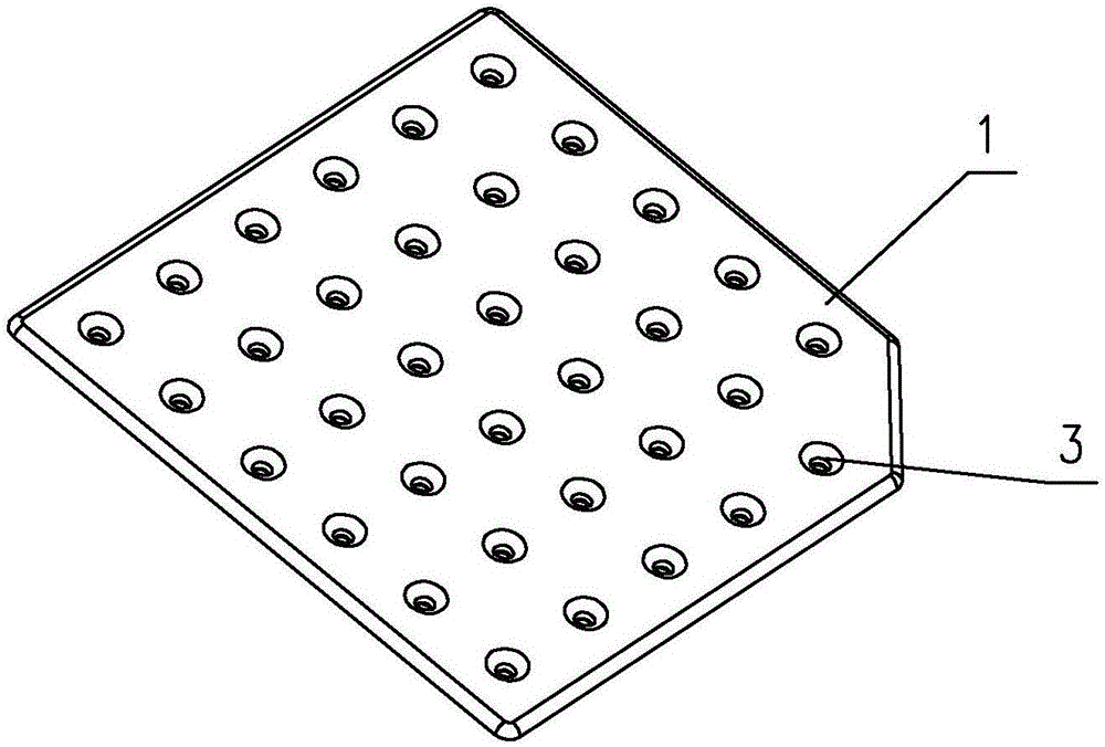
[0042] like Figure 1~5 As shown, it is an ultra-thin vapor chamber of the present invention, which includes a cover plate 1 and a bottom plate 2 that are sealed and connected at the periphery. A groove 12 is provided on the inner surface of the cover plate 1 to make the gap between the cover plate 1 and the bottom plate 2 A cavity 8 in a vacuum state is formed. In this embodiment, the bottom plate 2 is a flat plate, and the edge of the cover plate 1 is turned outward into a hem 11. In the cavity 8 and on the bottom surface of the groove 12, there are several Protrusions 3 arranged in an array, the protrusions 3 are hollow columns formed by pressing, the bottom surface of the protrusions 3 is flush with the lower surface of the flange 11, and the periphery of the bottom plate 1 is welded on the flange of the cover plate 2 to connect the cover plate 1 And the bottom plate 2, the protrusion 3 connects the cover plate 1 and the bottom plate 2 to support between the cover plate 1 ...

Embodiment 2

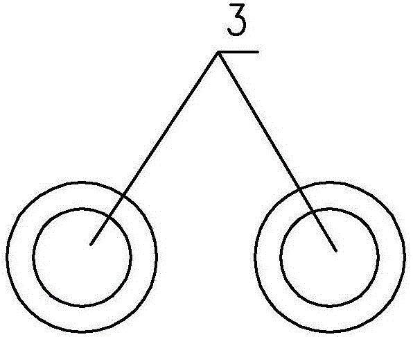
[0055] Such as Image 6 As shown, the difference between the ultra-thin vapor chamber of this embodiment and the ultra-thin vapor chamber of Embodiment 1 is that three or four protrusions 3 are close to each other to form a local void unit 6 with a hole 7 in the middle, which is relatively There are gaps between adjacent protrusions 3 , and each local gap unit 6 is distributed in an array. The diameter of the local void unit is 0.1-1mm.

[0056] The manufacturing process of this embodiment differs from the manufacturing process of Embodiment 1 in that: the specific position of the protrusions 3 on the metal sheet is different, so as to form three or four protrusions 3 close to each other to form a local void with a channel 7 in the middle unit 6, and each local void unit 6 is in the form of an array distribution.

Embodiment 3

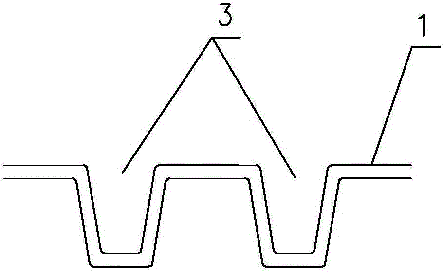
[0058] Such as Figure 7 As shown, the difference between the ultra-thin vapor chamber of this embodiment and the ultra-thin vapor chamber of embodiment 2 is that a capillary structure is laid on the inner surface of the bottom plate 2, and the capillary structure can be copper powder or copper mesh 5, In other embodiments, other capillary structures can also be used, and the protrusion 3 presses down on the capillary structure and is welded together with the capillary structure and the bottom plate 2 . The inner surface of the cavity is coated with a hydrophilic coating, that is, the outer wall of the protrusion, the top surface of the cavity and the copper mesh 5 are coated with a hydrophilic coating. The copper mesh absorbs the working fluid and has a siphon phenomenon. It can increase the heating and heat exchange area and increase the heat dissipation efficiency.

[0059] The manufacturing process of this embodiment is different from the manufacturing process of Example ...


PUM


Abstract

The invention discloses an ultrathin soaking plate and a manufacturing method thereof. The ultrathin soaking plate comprises a cover plate and a bottom plate, wherein the peripheral edge of the cover plate and the peripheral edge of the bottom plate are in sealed connection. A groove is formed in the inner surface of the cover plate so that a cavity in a vacuum state can be formed between the cover plate and the bottom plate. A plurality of protrusions arranged in an array manner are distributed in the cavity and located on the bottom face of the groove. The protrusions are hollow pillars formed in a pressing manner. The protrusions are connected with the cover plate and the bottom plate so that the protrusions can be supported between the cover plate and the bottom plate and used for heat transmission between the cover plate and the bottom plate. The outer walls of the protrusions serve as a medium for working fluid to flow towards the bottom plate from the cover plate when the working fluid is evaporated and condensed when encountering cold. The protrusions on the cover plate are in contact with the bottom plate and can support the cavity formed by the cover plate and the bottom plate and be used for heat transmission between the bottom plate and the cover plate; and the outer walls of the protrusions serve as the medium for the working fluid to flow towards the bottom plate from the cover plate when the working fluid is evaporated and condensed when encountering cold. By means of the ultrathin soaking plate and the manufacturing method of the ultrathin soaking plate, the thickness of the soaking plate can be reduced, the protrusions are formed in the pressing manner through a simple stamping technology, the manufacturing technology is simplified, the cost is low, and the ultrathin soaking plate is suitable for large-scale production.

Description

technical field [0001] The invention relates to a soaking plate, in particular to an ultra-thin soaking plate, and also to a manufacturing method of the ultra-thin soaking plate. Background technique [0002] The calculation speed of today's electronic products is getting faster and faster, but at the same time, the size of the products is required to be as small as possible. Smartphones, in particular, are getting thinner and thinner, constantly challenging the limit of thickness, which requires a lot of heat to be dissipated in the limited space in the phone. [0003] At present, the materials with the best heat transfer efficiency are heat pipes or vapor chambers with liquid phase change heat transfer. The thermal resistance of the liquid phase change heat transfer heat pipe is tens or even hundreds of times lower than that of metal copper or aluminum materials, and it is the best heat dissipation component in today's electronic products. Vapor chambers are more efficie...

Claims


Application Information

Patent Timeline
Patent Type & Authority Applications(China)
IPC IPC(8): F28D15/04
CPCF28D15/046F28D2021/0028
Inventor 白鹏飞陈平
Owner GUANGZHOU HUAZUAN ELECTRONICS TECH
Why Eureka
Try Eureka