Energy-saving and high-efficiency thermal desorption system for soil remediation

A soil remediation and thermal desorption technology, which is applied in the field of energy-saving and high-efficiency thermal desorption systems for soil remediation, can solve the problems of rapid heat loss and low utilization rate of heat of soil thermal desorption, so as to improve thermal desorption efficiency and avoid heat The effect of loss and avoidance of secondary pollution

Active Publication Date: 2019-12-20
MINGDA MARINE ENG CO LTD
View PDF9 Cites 3 Cited by
  • Summary
  • Abstract
  • Description
  • Claims
  • Application Information

AI Technical Summary

Problems solved by technology

[0005] The purpose of the present invention is to solve the problems of low heat utilization rate and rapid heat loss in the prior art, and propose an energy-saving and high-efficiency thermal desorption system for soil restoration

Method used


Image

  • Energy-saving and high-efficiency thermal desorption system for soil remediation
  • Energy-saving and high-efficiency thermal desorption system for soil remediation
  • Energy-saving and high-efficiency thermal desorption system for soil remediation

Examples


Embodiment 1

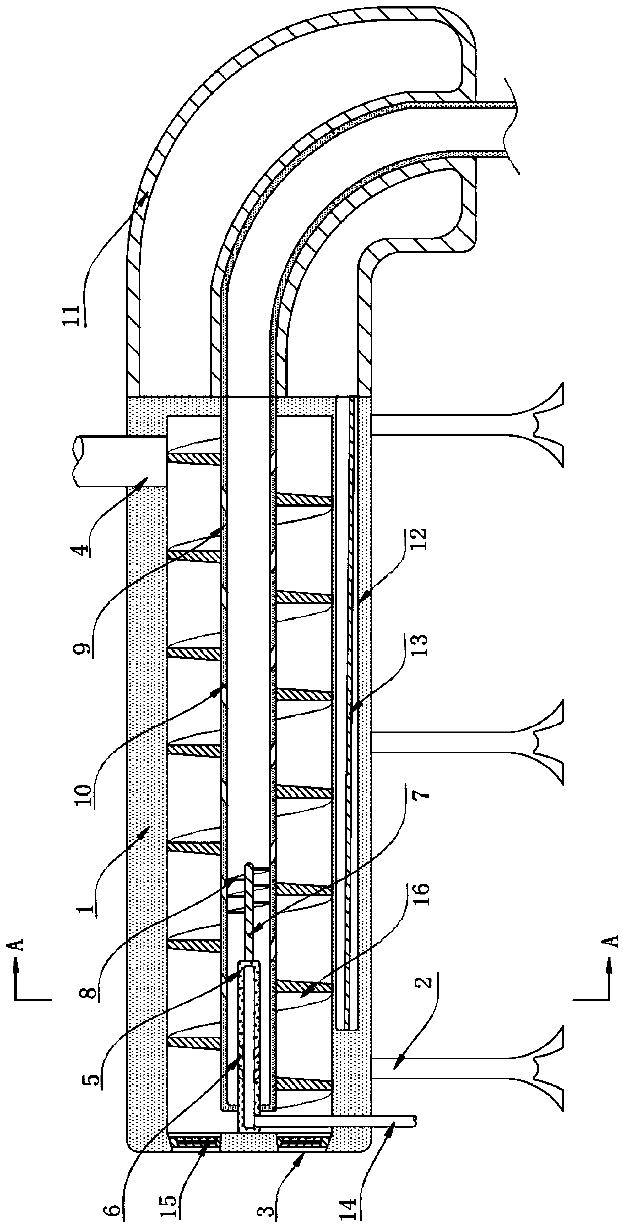
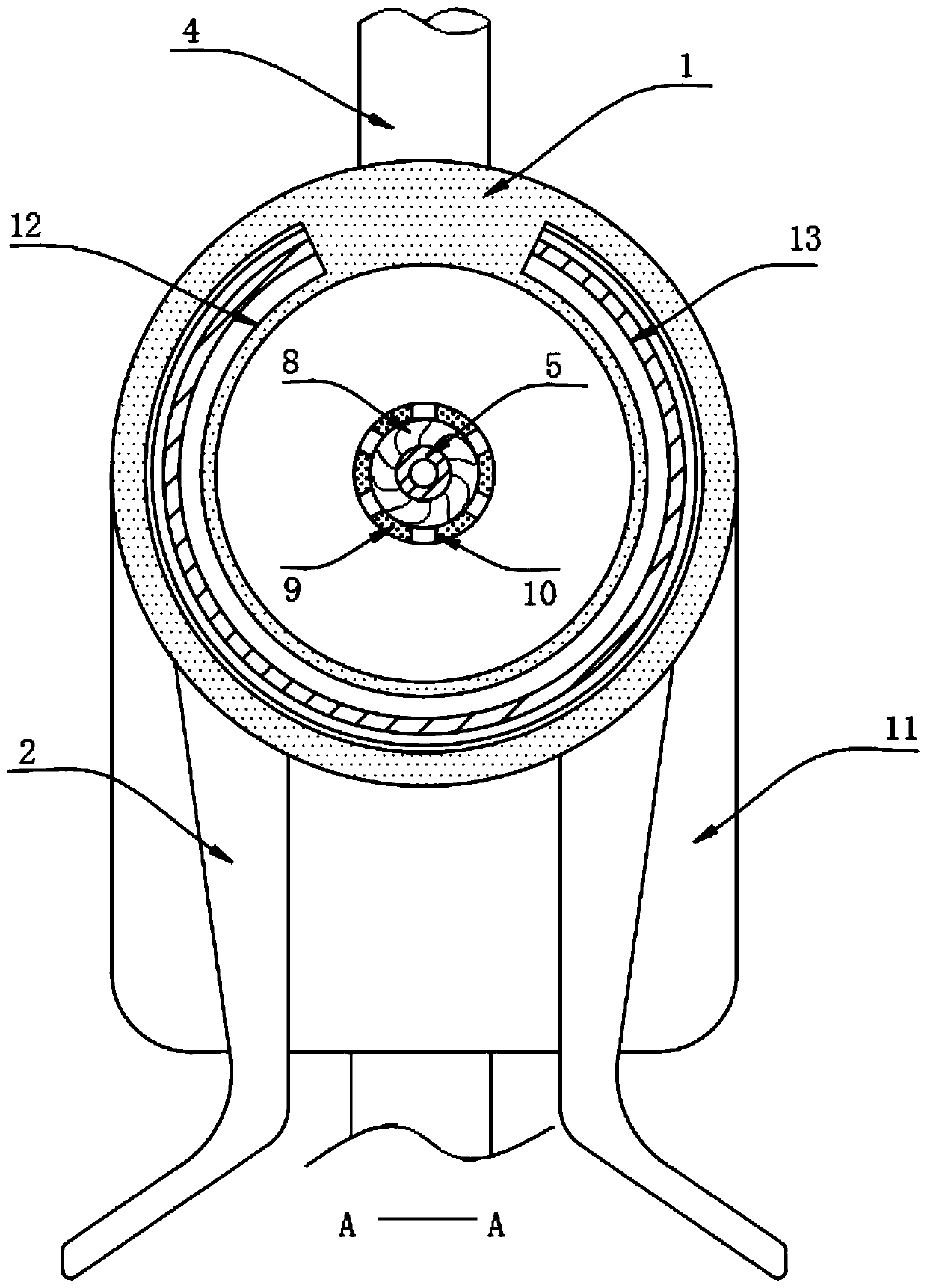
[0024] refer to Figure 1-2 , an energy-saving and high-efficiency thermal desorption system for soil remediation, comprising a cylindrical thermal desorption box 1, a plurality of groups of brackets 2 for supporting the thermal desorption box 1 are symmetrically fixed to the lower side of the outer wall of the thermal desorption box 1, and A group of discharge holes 3 are provided through the side wall of the stripping box 1, and a feed pipe 4 is inserted through the circumferential side wall of the thermal stripping box 1 away from the end of the discharge hole 3, and the end of the thermal stripping box 1 close to the discharge hole 3 The inner wall of the heat removal box 1 is welded with a fixed tube 5, and the circumferential side wall of the heat removal box 1 is inserted with an air inlet pipe 14 communicating with the inside of the fixed tube 5. The end of the cylinder 5 away from the discharge hole 3 is rotatably connected with a rotating shaft 7, and a group of driv...

Embodiment 2

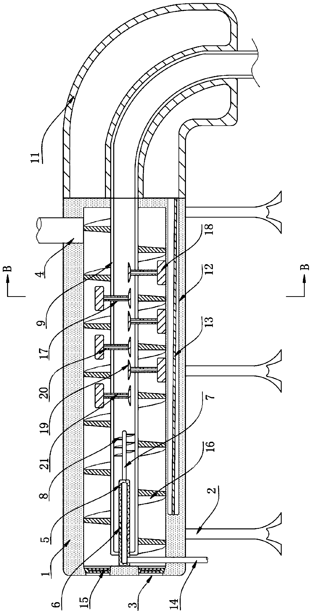
[0032] The difference between this embodiment and Embodiment 1 lies in the difference of the backflow device. In the present embodiment, the backflow device includes a plurality of ventilation pipes 17 that are slidably connected to the side walls of the auger rotating rod 9, and each ventilation pipe 17 is located on the side wall of the auger rotating rod. One end of the 9 inside is welded with a wing plate 19, and each vent pipe 17 is welded with a scraper 18 at one end outside the auger rotating rod 9, and the side wall of each vent pipe 17 is provided with a plurality of air inlet holes 20 and outlets. The air hole 21 and the air outlet hole 21 are closer to the inside of the auger rotating rod 9 than the corresponding air inlet hole 20; There is an air pressure difference between the two sides of the wing plate 19, so that the wing plate 19 can push the lower scraper 18 to insert into the soil.

[0033] When the high-temperature steam flows inside the auger rotating rod ...


PUM


Abstract

The invention discloses an energy-saving and high-efficiency thermal desorption system for soil remediation. The thermal desorption system comprises a cylindrical thermal desorption box, a plurality of groups of brackets for supporting the thermal desorption box which are symmetrically fixed on the lower side of the circumferential outer wall of the thermal desorption box, a set of discharge holeswhich are arranged through the side wall of the thermal desorption box, a feed pipe which is inserted through the circumferential side wall of the thermal desorption box far away from one end of thedischarge hole, a fixing cylinder which is welded on the inner wall of the thermal desorption box near one end of the discharge hole, and an air inlet pipe communicated with the inside of the fixing cylinder and inserted through the circumferential side wall of the thermal desorption box. The advantages are: the introduced high-speed and high-temperature airflow will drive the rotating blades to rotate, furthermore, the driving rotating blade drives an auger rotating rod to rotate, and the soil can be pushed through the pushing effect of the auger blade on the surface of the auger rotating rod, thus forming a continuous thermal desorption process, requiring no artificial soil replacement and no additional driving force, so that the whole process is more convenient, efficient and energy-saving.

Description

technical field [0001] The invention relates to the technical field of soil restoration, in particular to an energy-saving and high-efficiency thermal desorption system for soil restoration. Background technique [0002] With the increasing of soil organic pollution, the remediation of organic polluted solid waste is one of the key means of soil organic pollution recovery; the existing technologies used for remediation of organic polluted solid waste include: biological remediation process, chemical rinsing process, Gas phase extraction technology and thermal desorption method; [0003] Among them, thermal desorption technology is a technology that desorbs volatile substances from non-volatile substances through direct or indirect heating. It is one of the effective technologies for remediating polluted soil; unlike incineration, thermal desorption technology does not make organic pollution The components decompose, but the organic pollution components in the soil are heate...

Claims


Application Information

Patent Timeline
Patent Type & Authority Applications(China)
IPC IPC(8): B09C1/06
CPCB09C1/06
Inventor 肖琪琪
Owner MINGDA MARINE ENG CO LTD
Why Eureka
Try Eureka