Fingerprint identification structure and method and display device

A fingerprint identification and display device technology, which is applied to static indicators, character and pattern recognition, and acquisition/organization of fingerprints/palmprints. Achieve the effect of improving signal-to-noise ratio and accurate fingerprint recognition

Pending Publication Date: 2016-08-24
BOE TECH GRP CO LTD
View PDF6 Cites 44 Cited by
  • Summary
  • Abstract
  • Description
  • Claims
  • Application Information

AI Technical Summary

Problems solved by technology

[0003] However, due to the limitation of the size and performance of the photosensitive device in the photosensitive unit, the induced signal (photocurrent) generated by it is generally very small; in contrast, the noise signal generated by ambient lig

Method used


Image

  • Fingerprint identification structure and method and display device
  • Fingerprint identification structure and method and display device
  • Fingerprint identification structure and method and display device

Examples


Embodiment 1

[0045] Such as Figure 2 to Figure 14 As shown, the present embodiment provides a fingerprint recognition structure, which includes:

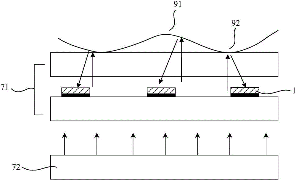
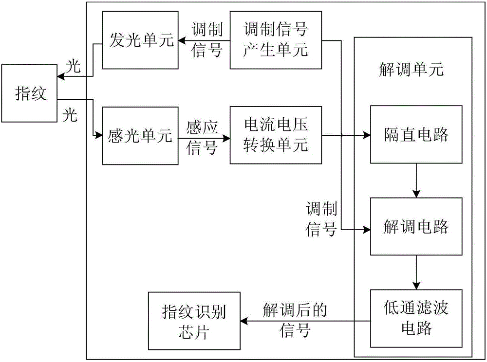
[0046] a light emitting unit for emitting light to the finger;

[0047] The photosensitive unit 1 is located at a position where it can receive the light emitted by the light-emitting unit reflected by the finger, and is used to generate a sensing signal according to the intensity of the received light;

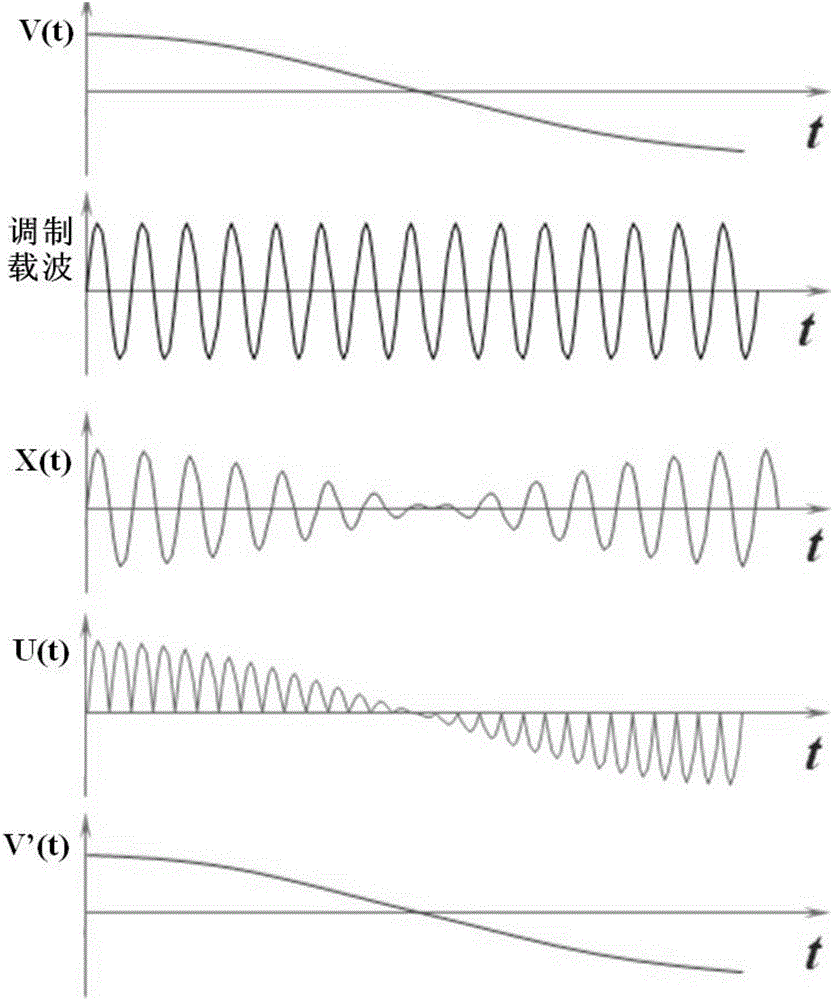
[0048] A modulating signal generating unit, configured to generate a modulating signal with a modulating frequency, and use the modulating signal to control the light emitting unit to flash and emit light at the modulating frequency;

[0049] The demodulation unit is connected with the photosensitive unit 1 and is used for demodulating the sensing signal.

[0050] The fingerprint identification structure of this embodiment includes at least one light-emitting unit capable of emitting light to the finger, and a plurality of photosensitive uni...


PUM


Abstract

The invention provides a fingerprint identification structure, a fingerprint identification method and a display device, belongs to the technical field of fingerprint identification, and can solve the problems of the exiting fingerprint identification method of low signal-to-noise ratio of an induction signal and poor fingerprint recognition accuracy. The fingerprint identification structure disclosed by the invention comprises a light emitting unit for emitting light to a finger, a light sensing unit arranged at the positions that light reflected by the finger and emitted by the light emitting unit can be received and used for generating the induction signal according to the intensity of the received light, a modulating signal generating unit for generating a modulating signal with modulation frequency and controlling the light emitting unit by the modulating signal to flicker by the modulation frequency, and a demodulation unit which is connected with the light sensing unit and used for demodulating the induction signal.

Description

technical field [0001] The invention belongs to the technical field of fingerprint identification, and in particular relates to a fingerprint identification structure and method, and a display device. Background technique [0002] With the development of technology, many display devices such as mobile phones and tablet computers begin to have a fingerprint recognition function. An existing fingerprint identification method such as figure 1 As shown, the display panel (take the liquid crystal display panel 71 as an example, a backlight unit 72 is provided outside the light incident surface) is provided with a plurality of photosensitive units 1, when the finger is pressed on the display panel, the light emitted by the display panel can be The light is reflected back to each photosensitive unit 1, and the valley 91 and ridge 92 of the fingerprint reflect light differently, so the induction signals (such as photocurrent) generated by the photosensitive unit 1 corresponding to ...

Claims


Application Information

Patent Timeline
IPC IPC(8): G06K9/00G06V10/141
CPCG06V40/1306G06F3/0412G06F3/042G06F3/04182G09G3/36G06V40/1318G06V10/141G02F1/13306G02F1/133512G02F1/133603
Inventor 王鹏鹏董学吕敬王海生吴俊纬丁小梁刘英明韩艳玲刘伟许睿李昌峰赵利军贾亚楠郭玉珍
Owner BOE TECH GRP CO LTD
Why Eureka
Try Eureka