Control apparatus for vehicle cooling apparatus

a control apparatus and cooling apparatus technology, applied in the direction of electric propulsion mounting, battery/fuel cell control arrangement, transportation and packaging, etc., can solve the problems of reducing the cooling efficiency, achieve the effect of improving the cooling efficiency of the cooling apparatus, efficient driving, and increasing the rotational speed of the first pump

Active Publication Date: 2021-01-14
TOYOTA JIDOSHA KK
View PDF5 Cites 0 Cited by
  • Summary
  • Abstract
  • Description
  • Claims
  • Application Information

AI Technical Summary

Benefits of technology

[0014]In the control apparatus according to the second aspect of the invention, the rotational speed of the first pump is increased with the increase of the difference between the temperature of the refrigerant of the PCU cooling unit and the temperature of the refrigerant of the T / A cooling unit. Thus, the first pump is efficiently driven whereby the cooling efficiency of the cooling apparatus is improved.
[0015]In the control apparatus according to the third aspect of the invention, the rotational speed of the second pump is increased with the increase of the rotational speed of the first pump. Thus, a heat transfer coefficient between the refrigerant of the PCU cooling unit and the heat exchanger is increased with the increase of the rotational speed of the first pump, thereby making it possible to efficiently transfer the heat generated in the power control unit, toward the drive-force transmitting apparatus.
[0016]The control apparatus according to the fourth aspect of the invention is applied to the vehicle that has a construction that allows the electric power to be supplied from the storage battery through the power control unit to an exterior of the vehicle, so that the electric power of the storage battery is supplied through the power control unit to an external device during an external power supply. During the external power supply, the temperature of the power control unit is increased whereby the temperature of the power control unit could be higher than the threshold temperature value, and the temperature of the refrigerant of the PCU cooling unit is increased whereby the temperature of the refrigerant of the PCU cooling unit could be higher than the temperature of the refrigerant of the T / A cooling unit. In the control apparatus according to the fourth aspect of the invention, when the temperature of the power control unit becomes higher than the threshold temperature value and the temperature of the refrigerant of the PCU cooling unit becomes higher than the temperature of the refrigerant of the T / A cooling unit, the first pump is driven to cause the heat generated in the power control unit to be transferred through the heat exchanger toward the drive-force transmitting apparatus whereby the power control unit is efficiently cooled.

Problems solved by technology

However, the pump is driven even when the temperature of the power control unit is reduced, so that the cooling efficiency could be reduced.

Method used


Image

  • Control apparatus for vehicle cooling apparatus
  • Control apparatus for vehicle cooling apparatus
  • Control apparatus for vehicle cooling apparatus

Examples


embodiment

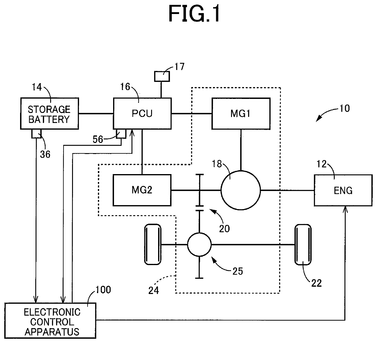
[0023]FIG. 1 is a view schematically showing construction of a vehicle 10 on which a cooling apparatus 80 is to be installed, wherein the present invention is applied to the cooling apparatus 80. The vehicle 10 is a hybrid vehicle in which a drive force is to be outputted from at least one of an engine 12 and a second electric motor MG2 that is included in a drive-force transmitting apparatus 24. The vehicle 10 includes, in addition to the above-described engine 12 and drive-force transmitting apparatus 24, a storage battery 14, a power control unit 16 (hereinafter referred to as “PCU 16”), drive wheels 22 and an electronic control apparatus 100. The drive-force transmitting apparatus 24 further includes a first electric motor MG1 in addition to the second electric motor MG2.

[0024]The engine 12 is constituted by, for example, an internal combustion engine such as a gasoline engine or a diesel engine.

[0025]The storage battery 14 is, for example, a chargeable / dischargeable secondary b...


PUM


Abstract

A control apparatus for a vehicle cooling apparatus that includes: a PCU cooling unit for cooling a power control unit controlling an electric motor; a T/A cooling unit for cooling a drive-force transmitting apparatus including the electric motor; and a heat exchanger for transferring heat between the PCU cooling unit and the T/A cooling unit. The T/A cooling unit includes a first pump for circulating a refrigerant of the T/A cooling unit, while the PCU cooling unit includes a second pump for circulating a refrigerant of the PCU cooling unit. The control apparatus includes a controlling portion configured to cause the first pump to be driven when a temperature of the power control unit is higher than a threshold temperature value and a temperature of the refrigerant of the PCU cooling unit is higher than a temperature of the refrigerant of the T/A cooling unit.

Description

[0001]This application claims priority from Japanese Patent Application No. 2019-127990 filed on Jul. 9, 2019, the disclosure of which is herein incorporated by reference in its entirety.FIELD OF THE INVENTION[0002]The present invention relates to a control apparatus for a cooling apparatus that is to be installed on a vehicle, and more particularly, to an improvement of a cooling efficiency of the cooling apparatus.BACKGROUND OF THE INVENTION[0003]There is known a cooling apparatus to be installed on a vehicle that includes (i) a drive-force transmitting apparatus including an electric motor and (ii) a power control unit, wherein the cooling apparatus includes a T / A cooling unit for cooling the drive-force transmitting apparatus, a PCU cooling unit for cooling the power control unit and a heat exchanger for transferring heat between the PCU cooling unit and the T / A cooling unit. An example of such a cooling apparatus is disclosed in Patent Document 1. In the cooling apparatus discl...

Claims


Application Information

Patent Timeline
Patent Type & Authority Applications(United States)
IPC IPC(8): B60K6/26B60K6/28H02K7/00H02K9/19H02K11/33
CPCB60K6/26B60K6/28B60Y2200/92H02K9/19H02K11/33H02K7/006B60K11/02B60L58/26Y02T10/62Y02T10/70B60K6/445B60K2001/006B60K2001/003
Inventor HASHIMOTO, TATSUYAMURAKAMI, YUKINORI
Owner TOYOTA JIDOSHA KK
Why Eureka
Try Eureka