Electrophoretic display method and device

Inactive Publication Date: 2006-06-06
CANON KK
View PDF17 Cites 44 Cited by
  • Summary
  • Abstract
  • Description
  • Claims
  • Application Information

AI Technical Summary

Benefits of technology

[0100]The present invention proposes two types of addressing methods for rewriting of a displayed image.
[0102]According to one display rewriting method, as shown in FIG. 5A, the driving voltages Vd1=Vd2=0 V are applied to the first and second driving electrodes 3, 4, and the driving voltage Vd3=+60 V is applied to the third driving electrode 5, whereby the migratory particles 6 are migrated away from the second substrate 2 toward the first substrate side. Then, desired display is performed pixel by pixel. Assuming that the pixel A should provide a black view, the driving voltage Vd1=+30 V is applied to the first driving electrode 3 and the driving voltage Vd2=30 V is applied to the second driving electrode 4. Also, assuming that the pixel B should provide a white view, the driving voltage Vd1=−30 V is applied to the first driving electrode 3 and the driving voltage Vd2=+30 V is applied to the second driving electrode 4. The migratory particles 6 are thereby migrated as desired (FIG. 5B). Subsequently, Vd3=−60 V is applied to the third driving electrode 5 again for transferring the migratory particles i.e., the display pattern, to the second substrate side as shown in FIG. 4B.
[0104]The other display rewriting method will now be described. According to this method, at the same time as applying the driving voltage Vd3=+60 V to the third driving electrode 5 to migrate the migratory particles 6 away from the second substrate 2 toward the first substrate side, the driving voltages are applied to the first driving electrode 3 and the second driving electrode 4 for writing.
[0105]More specifically, as shown in FIG. 5C, at the moment when the driving voltage Vd3=+60 V is applied to the third driving electrode 5, the driving voltage Vd1=+30 V is applied to the first driving electrode 3 and the driving voltage Vd2=−30 V is applied to the second driving electrode 4 for the pixel A that should provide a black view, while the driving voltage Vd1=−30 V is applied to the first driving electrode 3 and the driving voltage Vd2=+30 V is ap

Problems solved by technology

However, a current liquid crystal display has problems, which are not yet overcome to a satisfactory level, in that characters displayed on a screen become hard to perceive depending on the angle of viewing the screen and the presence of reflected light, and a burden is imposed on a viewer's visual organ due to, e.g., flickering and low luminance of a light source.
Also, the display-screen representation using a CRT can provide the contrast and luminance at a satisfactory high level as compared with the case of using a liquid crystal display, but it accompanies flickering, etc. and hence also cannot be regarded as having a sufficient display quality as compared with the hard-copy representation described below.
Additionally, the display-screen representation using a CRT entails a large and heavy body, and is therefore very poor in portability.
When information is displayed using a display unit, there occurs not only the above-mentioned problems with regard to display quality, but also another problem that a resolution achieved by the display-screen representation is generally about 120 dpi at maximum, which is fairly lower than that in the case of printing out information on paper (usually not lower than 300 dpi).
Thus, the hard-copy representation has various merits over the display-screen representation so long as moving images or frequent rewriting is not needed, but it is disadvantageous in consuming a great deal of paper.
Such a matrix is employed in display portions of some prepaid cards, but still has problems that the contrast is not so high and the number of times at which an image can be recorded and erased repeatedly is relatively small, i.e., on the order of 150 to 500.
In the above-described electrophoretic display device, however, a dye and a coloring material in the form of ions, for example, must be mixed in the dielectric liquid, and the presence of such a coloring material tends to act as an unstable factor in the electrophoretic operation because of giving rise to a new transfer of charges.
This tendency may deteriorate the perfor

Method used


Image

  • Electrophoretic display method and device
  • Electrophoretic display method and device
  • Electrophoretic display method and device

Examples


example 1

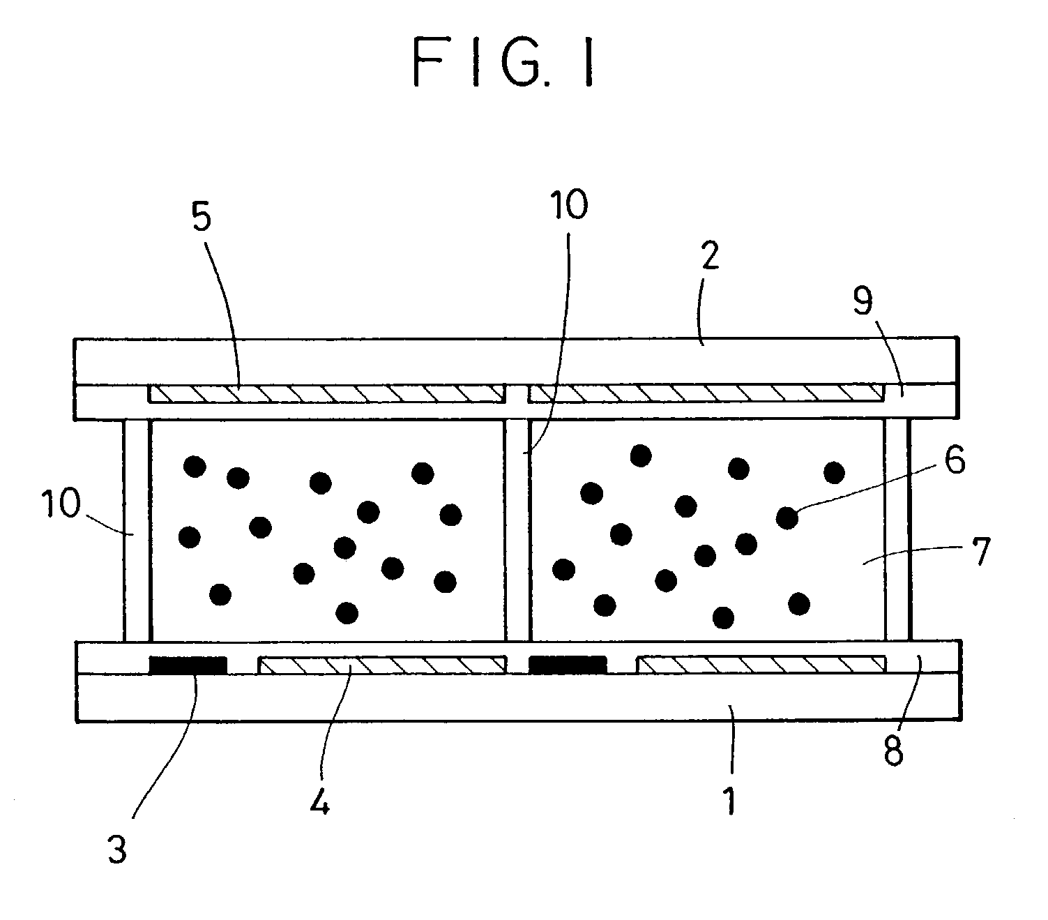
[0134]In this Example, a (3×3)-matrix display cell having the cell construction shown in FIG. 1 was fabricated and operated in accordance with the above-described Passive Matrix Addressing Method 1 to implement the passive matrix addressing based on bi-directional writing. The bi-directional writing is difficult to realize with the construction disclosed in the above-cited Japanese Patent Publication No. (by PCT application) 8-507154, and is one feature specific to the present invention. With this feature, the display cell of this Example is able to perform the bi-directional writing, i.e., changes from a white to black view and writing from a black to white view.

[0135]FIG. 14 is a plan view of the (3×3)-matrix display cell thus fabricated. The size of one pixel was 1 mm×1 mm, and the area ratio of the first driving electrode to the second driving electrode was 20:80.

[0136]A method of manufacturing the cell will be briefly described below with reference to FIGS. 1 and 14. First, an ...

example 2

[0160]In this Example 2, the (3×3)-matrix display cell employed in above Example 1 was operated in accordance with the above-described Passive Matrix Addressing Method 2 to implement the passive matrix addressing based on bi-directional writing.

[0161]A display cell used in this Example has exactly the same construction as that used in above Example 1 (plan view being shown in FIG. 14), and therefore an explanation of the manufacturing process is omitted herein.

[0162]The addressing method in this Example will be described below.

[0163]As with above Example 1, the first driving electrodes 3 were used as first data-signal electrode lines (D11–D13), the second driving electrodes 4 were used as second data-signal electrode lines (D21–D23), and the third driving electrodes 5 were used as scan-signal electrode lines (S1–S3).

[0164]FIG. 16A is a time chart of driving voltages applied to the first and second data-signal electrode lines and the scan-signal electrode lines, and FIG. 16B shows a ...

example 3

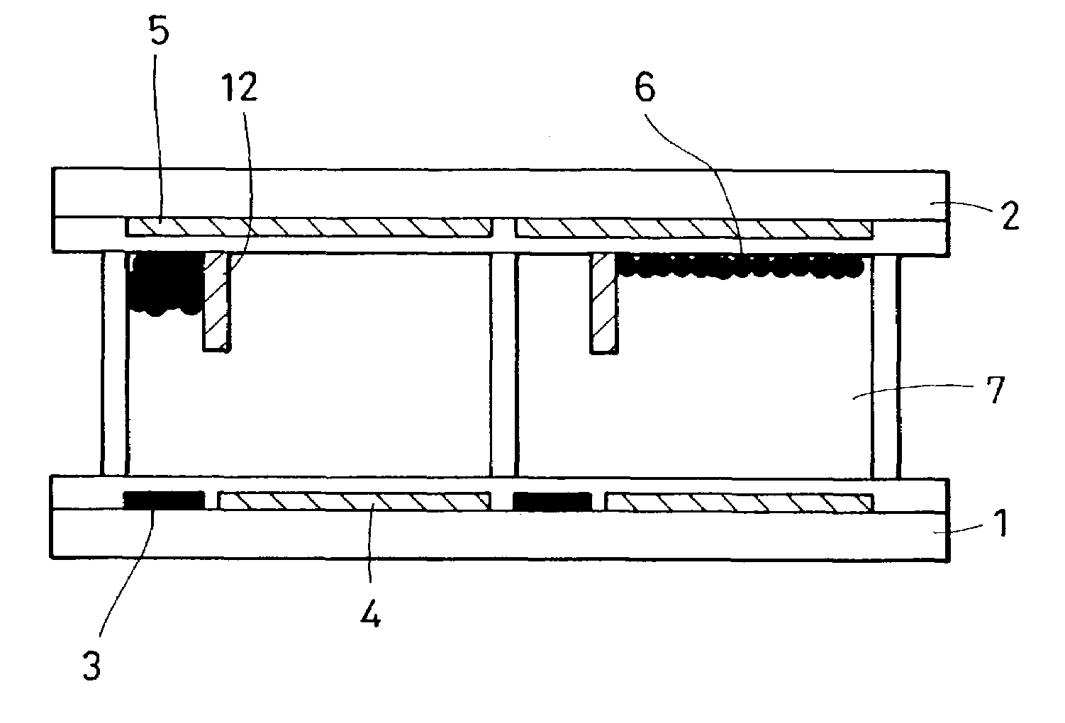
[0168]In this Example 3, a (3×3)-matrix display cell having the cell construction shown in FIG. 10, wherein the barriers 12 were provided on the surfaces of the third driving electrodes 5 arranged on the underside of the second substrate 2, was fabricated and operated with the passive matrix addressing based on bi-directional writing.

[0169]A plan view of the (3×3)-matrix display cell thus fabricated was the same as that shown in FIG. 14. As with above Example 1, the size of one pixel was 1 mm×1 mm, and the area ratio of the first driving electrode 3 to the second driving electrode 4 was 20:80.

[0170]A method of manufacturing the cell will be briefly described below with reference to FIGS. 10 and 14.

[0171]First, an insulating layer 8 made of an acrylic resin containing a white pigment, such as alumina, dispersed therein was formed on an overall surface of a first substrate 1 formed of a PET film having a thickness of 200 μm. Then, an ITO film was formed as a second driving electrode 4...


PUM


Abstract

An electrophoretic display device includes a first substrate, first and second driving electrodes arranged on the first substrate, a second substrate arranged in an opposing relation to the first substrate and a third driving electrode arranged on the second substrate. A transparent dielectric liquid is filled between the first substrate and the second substrate, and a plurality of migratory particles are dispersed in the transparent dielectric liquid. A barrier is disposed on a surface of the third driving electrode arranged on the second substrate and is situated in an opposing relation to a boundary between the first driving electrode and the second driving electrode.

Description

[0001]This is a divisional application of application Ser. No. 09 / 832,210, filed on Apr. 11, 2001 now U.S. Pat. No. 6,738,039.BACKGROUND OF THE INVENTION[0002]1. Field of the Invention[0003]The present invention relates to an electrophoretic display method and device in which charged migratory particles are migrated for display of an image.[0004]2. Description of the Related Art[0005]Recently, with rapid development of information equipment, the amount of data included in various kinds of information has increased more and more, and output of the information has been made in various forms. Generally, information is outputted in two primary ways, i.e., display-screen representation using a CRT or a liquid crystal, and hard-copy representation on paper using a printer or the like. In the display-screen representation, increasing needs exist for a display device that has low power consumption and is thin. Above all, a liquid crystal display has been actively developed and commercialize...

Claims


Application Information

Patent Timeline
IPC IPC(8): G09G3/34G02F1/167G09G3/20
CPCG02F1/167G09G3/3446G09G3/2074G09G2320/0209G09G2300/06G09G2310/06
Inventor GODEN, TATSUHITO
Owner CANON KK
Why Eureka
Try Eureka