Motor drive control apparatus

a technology of motor drive and control apparatus, which is applied in the direction of electric generator control, dynamo-electric converter control, dynamo-electric gear control, etc., can solve the problem of small maximum torque in the high rotational speed rang

Inactive Publication Date: 2007-01-16
DENSO CORP
View PDF41 Cites 44 Cited by
  • Summary
  • Abstract
  • Description
  • Claims
  • Application Information

AI Technical Summary

Benefits of technology

[0006]The object of the present invention is to provide a motor drive controller

Problems solved by technology

Also, in a high rotational speed region of the motor, a counter electromotive force is large, which means that if the voltage applied to the motor is low, maximum torque for the high rot

Method used


Image

  • Motor drive control apparatus
  • Motor drive control apparatus
  • Motor drive control apparatus

Examples


Embodiment Construction

[0027]Embodiments of the present invention will now be described below based on the drawings.

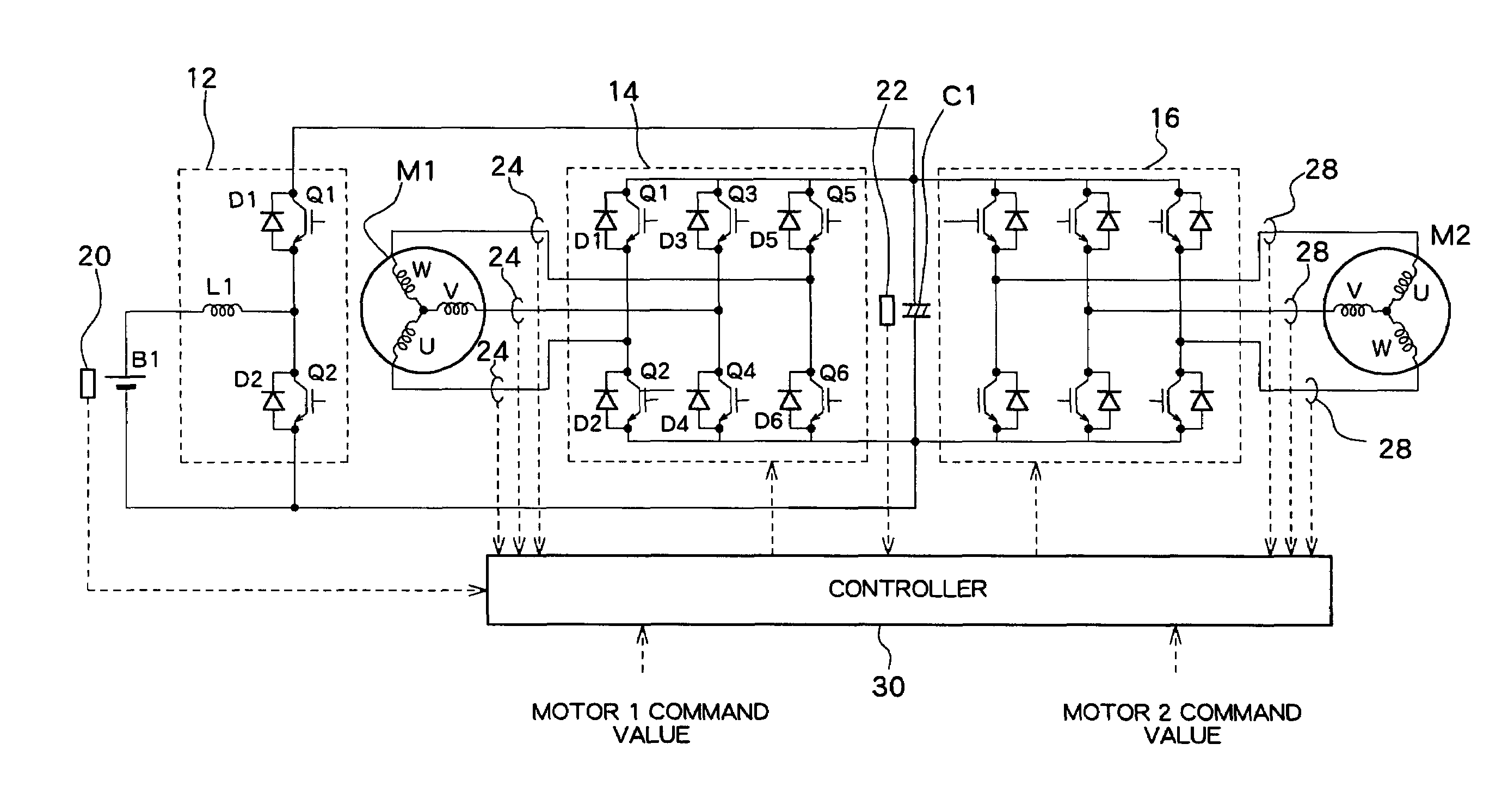
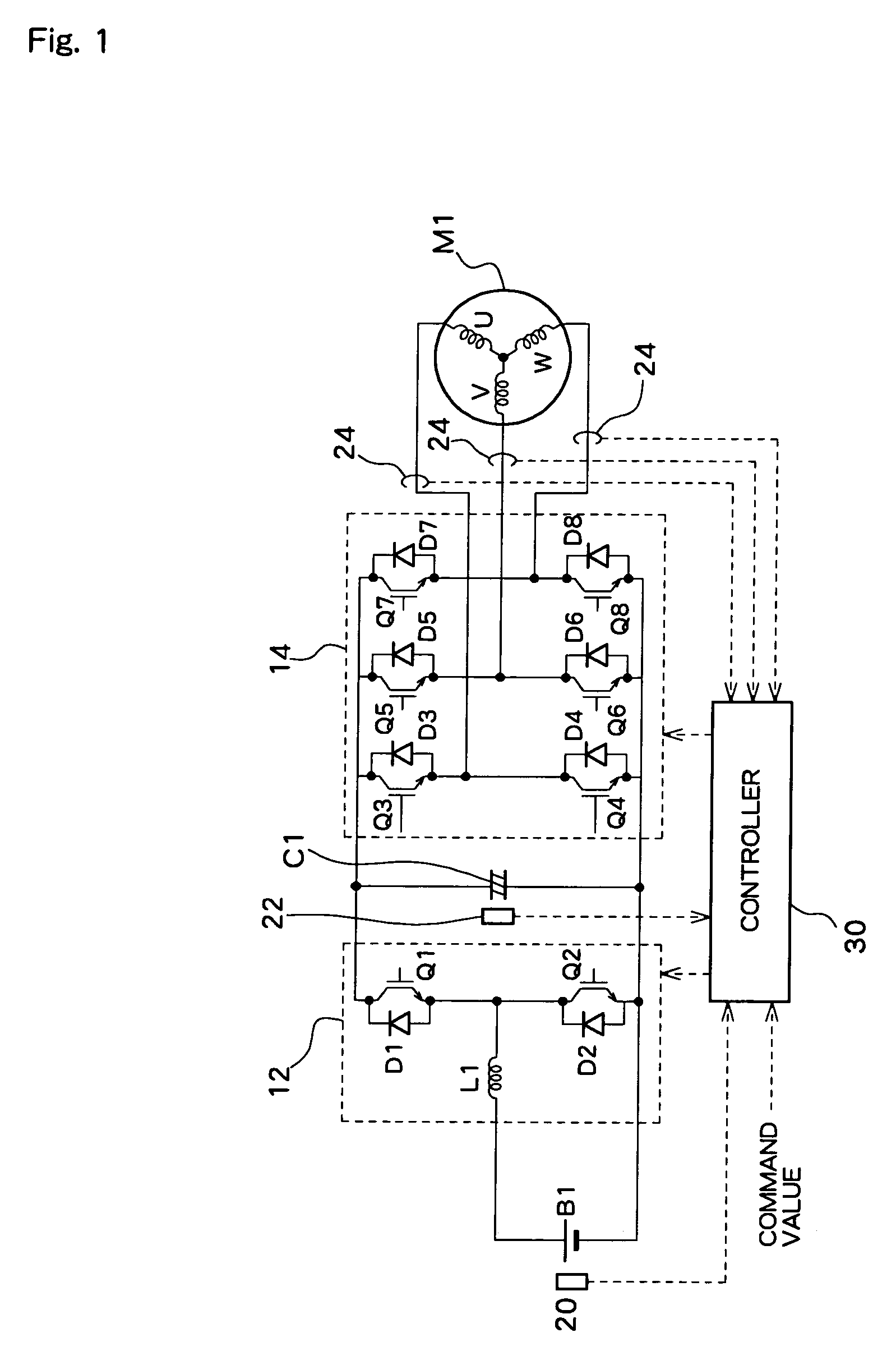
[0028]FIG. 1 is a drawing showing the structure of one embodiment, where a battery B1, being a dc power source, is a secondary battery such as a nickel metal hydride (NiMH) or lithium ion battery. One end of a reactor L1 is connected to the positive electrode of the battery B1. The other end of the reactor L1 is connected to an intermediate point of NPN transistors Q1 and Q1 that are connected in series (connection point of the emitter of transistor Q1 and the collector of transistor Q2). The collector of transistor A1 is connected to a power source line while the emitter of transistor Q2 is connected to earth. Diodes D1 and D2 are respectively arranged across the emitter and collector of each of the transistors Q1 and Q2 to allow current to flow from an emitter side to a collector side. A converter 12 is thus constituted by the reactor L1, transistors Q1 and Q1, and the diodes, D1 and D2.

[0...


PUM


Abstract

On end of a reactor (L1) is connected to a positive electrode of a battery (B1) and the other end is connected to a power line via a transistor (Q1) and to the ground via a transistor (Q2). By PWM control of the transistors (Q1, Q2), an arbitrary increased voltage is obtained in the power line. It is possible to obtain an optimal inverter input voltage (power line voltage) according to the motor drive state, thereby increasing efficiency. Thus, it is possible to optimize the inverter input voltage according to the motor drive condition.

Description

TECHNICAL FIELD[0001]The present invention relates to a motor drive controller for supplying output from a dc power source to a motor through an inverter, and controlling drive of the motor.BACKGROUND ART[0002]Conventionally, a hybrid vehicle or an electric vehicle has a motor for traveling, and traveling is accomplished by driving this motor. A battery is therefore required to supply electrical power to the motor, and a high voltage battery of a few hundred volts is normally used in order to efficiently supply electrical power to a high output motor. On the other hand, various components (accessories) operated by electrical power are mounted in the vehicle, and a 12V battery (low voltage battery) is used as a battery for these accessories. High voltage output of the high voltage battery is then stepped down to 12V using a converter to charge the low voltage battery.[0003]Also, in a high rotational speed region of the motor, a counter electromotive force is large, which means that i...

Claims


Application Information

Patent Timeline
IPC IPC(8): H02P27/04B60L11/18H02M7/48H02P6/08H02P21/02H02P23/02H02P27/06H02P27/08H02P27/14
CPCB60L11/1803H02M7/48H02P27/06H02P27/14H02P27/08H02M2001/007Y02T10/7005H02P2201/03H02P2201/07Y02T10/642B60L50/51Y02T10/64Y02T10/70H02M1/007
Inventor SATO, EIJISHAMOTO, SUMIKAZUKOMATSU, MASAYUKIOKI, RYOJINAKAMURA, MAKOTO
Owner DENSO CORP
Why Eureka
Try Eureka