Apparatus for driving LEDs using high voltage

a technology of led lights and high voltage, applied in the direction of electric variable regulation, process and machine control, instruments, etc., can solve the problems of reducing efficiency, costing more, and difficult to miniaturize an led-based lighting device, so as to achieve low power loss, efficient driving of led strings, and high input voltage

Inactive Publication Date: 2014-09-30
VASTVIEW TECH
View PDF16 Cites 9 Cited by
  • Summary
  • Abstract
  • Description
  • Claims
  • Application Information

AI Technical Summary

Benefits of technology

[0011]The present invention has been made to provide an apparatus that can efficiently drive a LED string with low power loss using high input voltage. In accordance with the present invention, the apparatus comprises a plurality of LEDs divided into a plurality of LED segments connected in series and a plurality of three-terminal voltage controlled current limiting devices associated with the LED segments.
[0016]According to a second preferred embodiment of the present invention, a power-loss reduction circuit is further inserted between the common node and the current source so as to reduce the power loss in the current source because of the high voltage at the common node. The power-loss reduction circuit has a plurality of LEDs divided into a plurality of LED segments controlled by an LED controlling circuit. The LED segments in the power-loss reduction circuit are connected in series between the common node and the current source.

Problems solved by technology

The need of a voltage conversion device reduces the efficiency, costs more and also makes it difficult to miniaturize an LED-based lighting device.

Method used


Image

  • Apparatus for driving LEDs using high voltage
  • Apparatus for driving LEDs using high voltage
  • Apparatus for driving LEDs using high voltage

Examples


Embodiment Construction

[0039]The accompanying drawings are included to provide a further understanding of the invention, and are incorporated in and constitute a part of this specification. The drawing illustrates embodiments of the invention and, together with the description, serves to explain the principles of the invention.

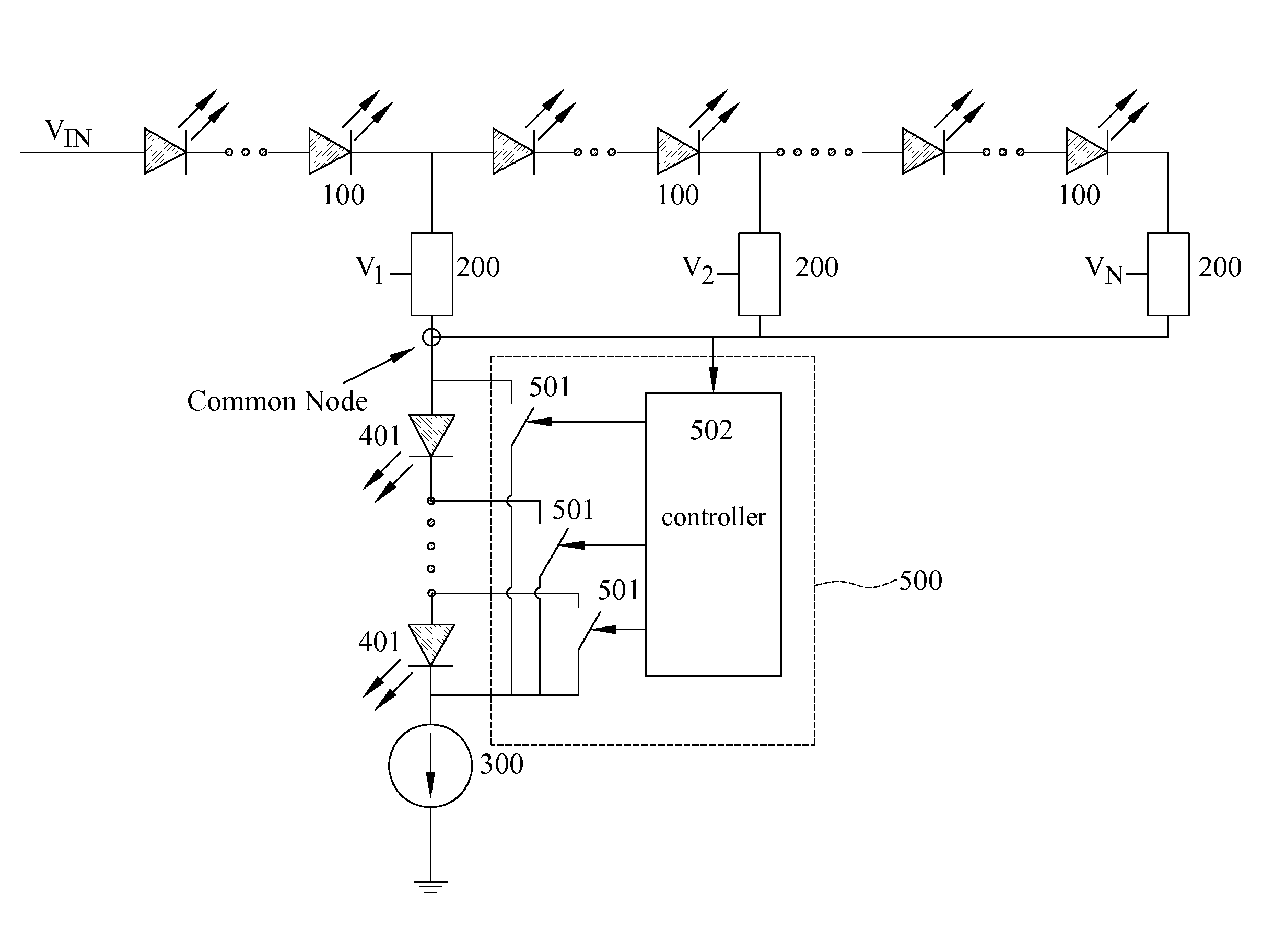
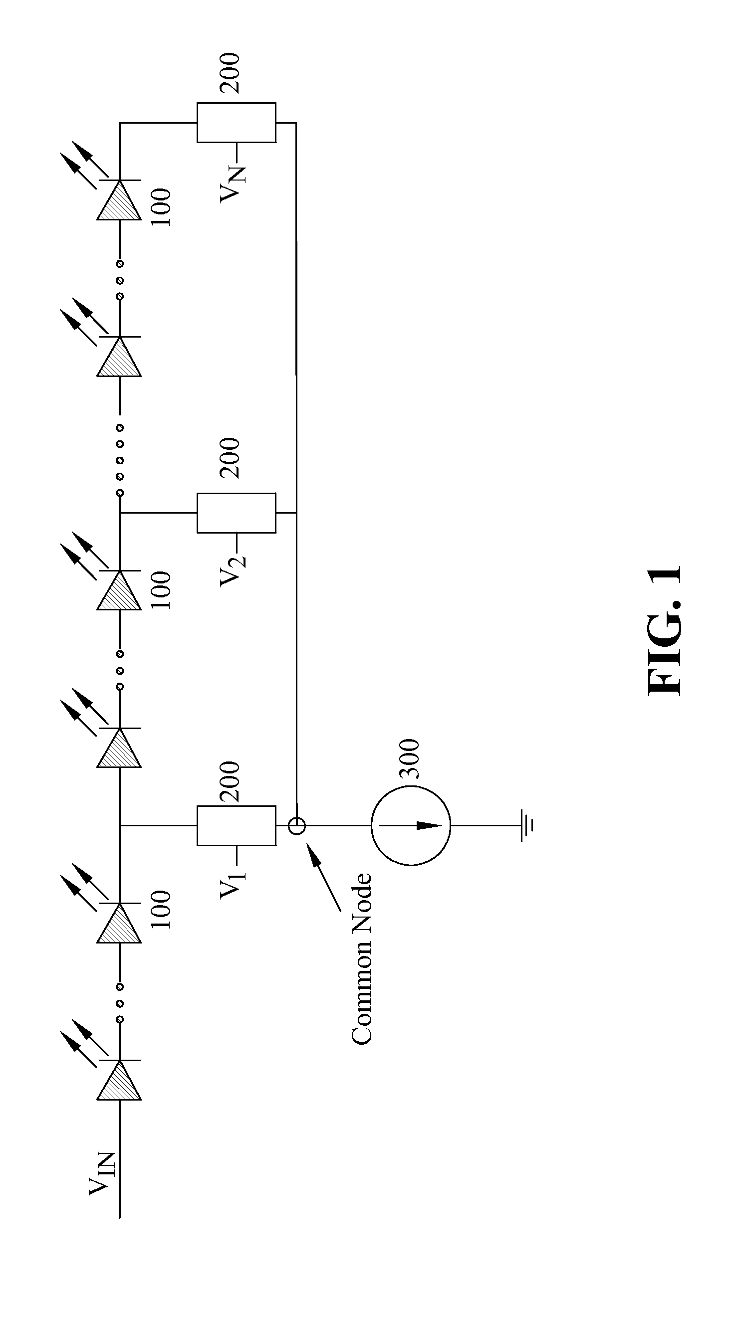
[0040]FIG. 1 shows a block diagram of an apparatus for driving LEDs using high voltage according to a first preferred embodiment of the present invention. In the embodiment, the apparatus comprises a plurality of LEDs connected in series. The plurality of LEDs is divided into a plurality of LED segments 100. Each LED segment 100 has a positive end and a negative end connected respectively to the negative end of its preceding LED segment and the positive end of its following LED segment.

[0041]As can be seen in FIG. 1, the negative end of each LED segment is also connected to a first terminal of a three-terminal voltage controlled current limiting device 200. The second terminal of th...


PUM


Abstract

An apparatus for driving LEDs using high voltage includes a plurality of LEDs divided into a plurality of LED segments connected in series and a plurality of three-terminal voltage controlled current limiting devices. Each of the current limiting devices is associated with one of the LED segments and has a first terminal connected to a negative end of the associated LED segment, a second terminal applied with a bias voltage and a third terminal connected to a common node. A current source is connected between the common node and ground. A power-loss reduction circuit having a plurality of LEDs controlled by an LED controlling circuit may further be inserted between the common node and the current source to reduce the power loss in the current source because of the high voltage at the common node.

Description

BACKGROUND OF THE INVENTION[0001]1. Field of the Invention[0002]The present invention relates generally to light emitting diode (LED) based lighting apparatus, and more particularly to an apparatus for driving an LED based lighting apparatus using high input voltage.[0003]2. Description of Related Arts[0004]LEDs are semiconductor-based light sources often employed in low-power instrumentation and appliance applications for indication purposes in the past. The application of LEDs in various lighting units has also become more and more popular. For example, high brightness LEDs have been widely used for traffic lights, vehicle indicating lights, and braking lights. In recent years, high voltage LED-based lighting apparatus have been developed to replace the conventional incandescent and fluorescent lamps.[0005]An LED has an I-V characteristic curve similar to an ordinary diode. When the voltage applied to the LED is less than a forward voltage, only very small current flows through th...

Claims


Application Information

Patent Timeline
Patent Type & Authority Patents(United States)
IPC IPC(8): H05B37/02H05B44/00
CPCH05B33/0845H05B33/0815H05B33/083H05B45/48
Inventor CHU, HUNG-CHILIN, CHANG-CHENGSHEN, YUHREN
Owner VASTVIEW TECH
Why Eureka
Try Eureka