Drive apparatus, control method for the drive apparatus, storage medium storing a program controlling the drive apparatus, and power output apparatus

Inactive Publication Date: 2006-09-05
DENSO CORP
View PDF49 Cites 41 Cited by
  • Summary
  • Abstract
  • Description
  • Claims
  • Application Information

AI Technical Summary

Benefits of technology

[0006]It is an object of the drive apparatus of the present invention to further improve the energy efficiency of the overall apparatus by driving a DC/DC converter at a more efficient switching frequency. Furthermore, it is an object of the

Problems solved by technology

However, in this sort of power output apparatus, there is a problem in some instances where the DC/DC converter is not necessarily driven at an optimum switching frequency and the energy efficiency drops.
Therefore, when driving the DC/DC converter at a fixed swit

Method used


Image

  • Drive apparatus, control method for the drive apparatus, storage medium storing a program controlling the drive apparatus, and power output apparatus
  • Drive apparatus, control method for the drive apparatus, storage medium storing a program controlling the drive apparatus, and power output apparatus
  • Drive apparatus, control method for the drive apparatus, storage medium storing a program controlling the drive apparatus, and power output apparatus

Examples


first embodiment

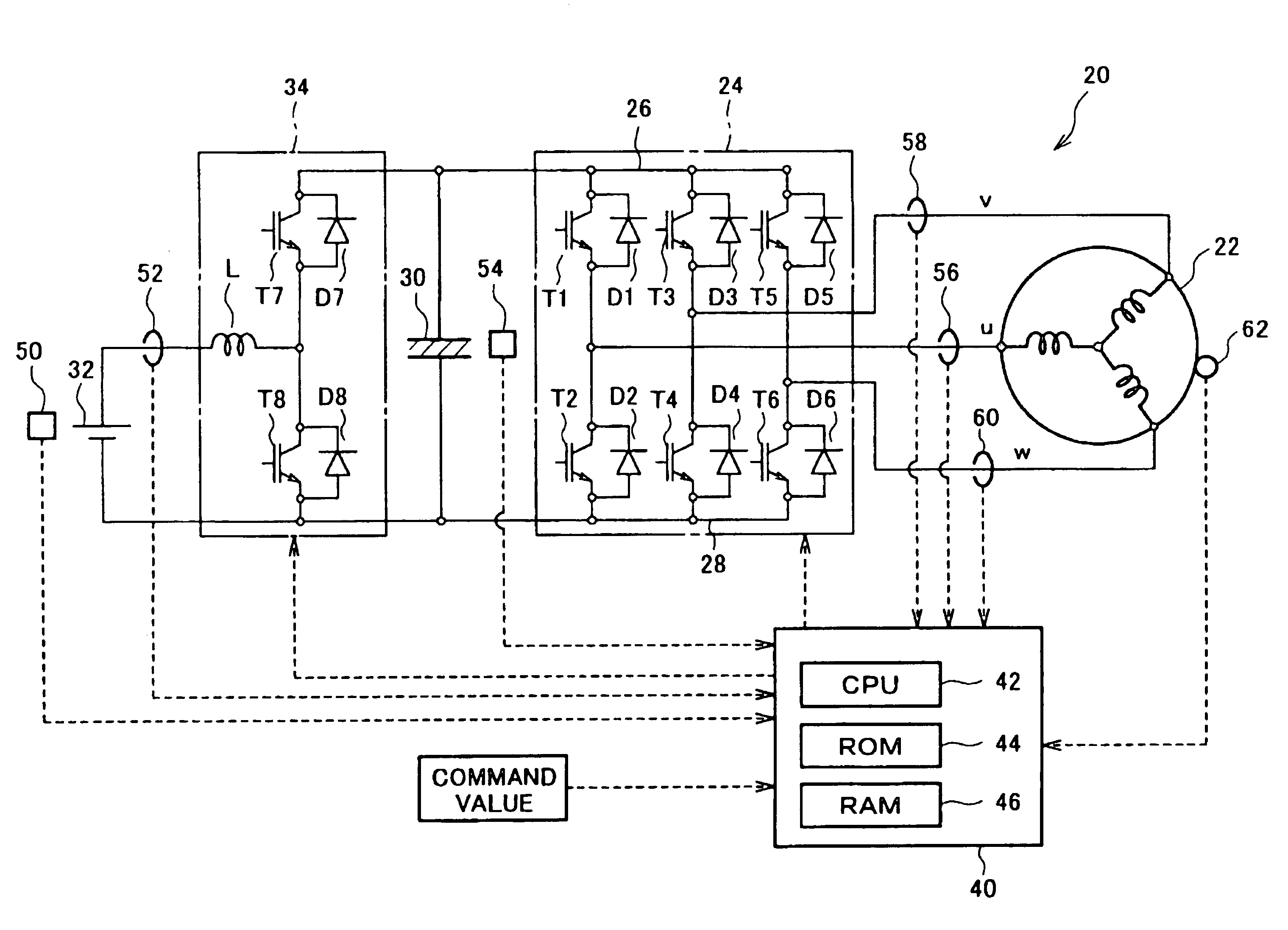
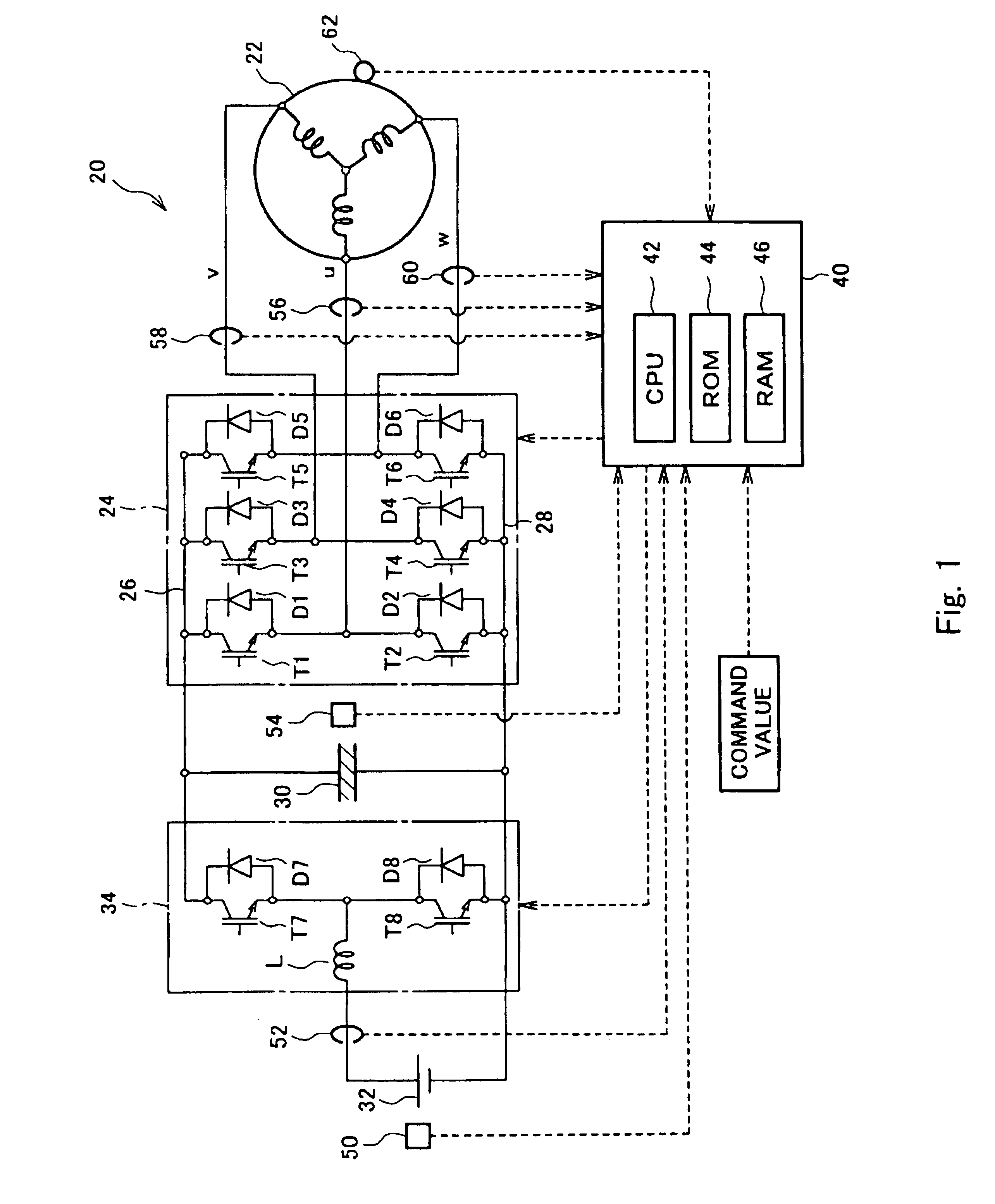
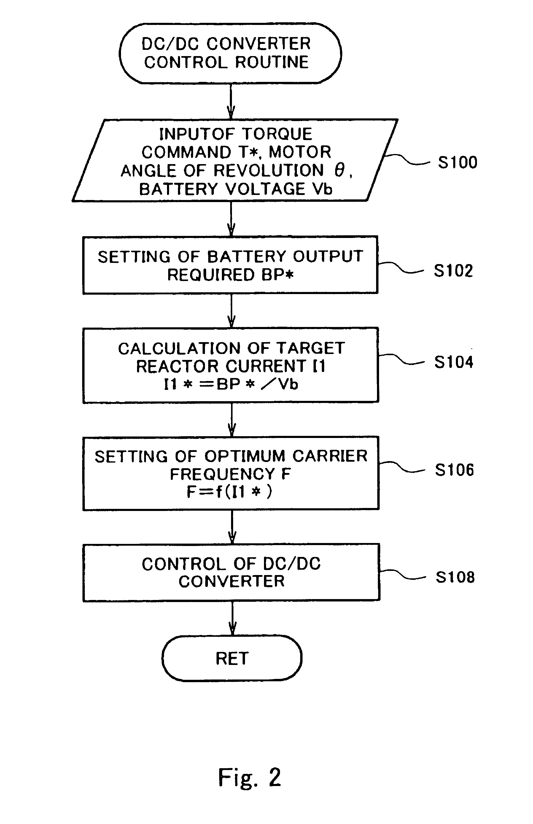
[0048]Next, embodiments of the present invention will be described using embodiments. FIG. 1 shows an overall configuration of the power output apparatus 20, which is the preferred first embodiment of the present invention. The power output apparatus 20 of this embodiment comprises a motor 22 that is rotationally driven by a three-phase alternating current, an inverter circuit 24 capable of converting DC power into three-phase AC power and supplying it to the motor 22, a capacitor 30 that is connected to a positive bus line 26 and a negative bus line 28 of the inverter circuit 24, a battery 32 capable of being charged and discharged, a DC / DC converter 34 capable of performing DC / DC conversion on the DC voltage from the battery 32 and supplying it to the capacitor 30, and an electronic control unit 40 for setting a switching frequency (carrier frequency) for the DC / DC converter 34 and controlling the overall apparatus.

[0049]The motor 22 is, for example, configured as a synchronous ge...

second embodiment

[0065]The step-up / down operation based on each phase coil of the motor 122 and the transistors T1 to T6 of the inverter circuit 124 will be described next. FIG. 6 is a circuit diagram of the power output apparatus 120 of the second embodiment focusing on phase u of the three-phase coils of the motor 122. When the state in which the transistor T2 for phase u of the inverter circuit 124 is turned ON is now considered, a short circuit shown by the broken lines in the figure is formed in this state so that phase u of the three-phase coils of the motor 122 functions as a reactor. When the transistor T2 is turned OFF from this state, the energy stored in phase u of the three-phase coils functioning as the reactor is stored into the capacitor 130 by the circuit shown by the solid lines in the figure. The voltage at this time can be set higher than the supply voltage of the battery 132. On the other hand, the battery 132 can be charged by the potential of the capacitor 130 using this circui...


PUM


Abstract

An electronic control unit (40) calculates the current flowing through a reactor (L) by dividing an output required BP* of a battery (32), obtained from converting the power required by a motor (22), by a terminal voltage Vb of the battery (32). A carrier frequency (optimum carrier frequency) is set for transistors (T7, T8) where the loss of a DC/DC converter (34) is minimized from the calculated current, and the DC/DC converter (34) is controlled at the set switching frequency.

Description

BACKGROUND OF THE INVENTION[0001]1. Field of the Invention[0002]The present invention relates to a drive apparatus, a control method for the drive apparatus, a storage medium in which is stored a program controlling the drive apparatus, and a power output apparatus.[0003]2. Description of the Prior Art[0004]Heretofore, an apparatus has been proposed for this type of power output apparatus comprising a capacitor that is connected to a positive bus line and a negative bus line of an inverter circuit for applying a three-phase alternating current to a motor, and a DC / DC converter capable of performing DC / DC conversion on the power from the DC power source and supplying to the capacitor. In this power output apparatus, a charge is stored into the capacitor by using a reactor for temporarily storing the current of the DC power source as energy and stepping up the voltage of the DC power source, and the motor is driven with this charged capacitor as a DC power source. The voltage step-up ...

Claims


Application Information

Patent Timeline
IPC IPC(8): H02M7/5387H02M7/68H02J7/14H02J7/24H02J7/34H02M3/156H02M3/335H02M7/48H02P6/06H02P6/08H02P6/17H02P6/28H02P27/06
CPCH02P27/08H02J7/1438H02J7/242H02P27/06H02P6/085H02P27/042H02J7/345H02J7/24H02P27/048
Inventor NAKAMURA, MAKOTOSATO, EIJIOKI, RYOJIKOMATSU, MASAYUKISHAMOTO, SUMIKAZU
Owner DENSO CORP
Why Eureka
Try Eureka