Toroidal low-field reactive gas source

a reactive gas and low-field technology, applied in plasma welding apparatus, ion beam tubes, manufacturing tools, etc., can solve the problems of low kinetic energy, microwave and inductively coupled plasma sources that require expensive and complex power delivery systems, and require the use of high-voltage drive coils, so as to efficiently drive the primary winding

Inactive Publication Date: 2007-01-09
MKS INSTR INC
View PDF188 Cites 42 Cited by
  • Summary
  • Abstract
  • Description
  • Claims
  • Application Information

AI Technical Summary

Benefits of technology

[0014]A principal discovery of the present invention is that switching semiconductor devices can be used to efficiently drive the primary winding of a power transformer that couples electromagnetic energy to a plasma so as to form a secondary circuit of the transformer. It is another principal discovery of this invention that an inductively-driven toroidal plasma source can be constructed with a metallic plasma chamber.

Problems solved by technology

For example, some applications require the use of ions with low kinetic energy (i.e. a few electron volts) because the material being processed is sensitive to damage.
However, microwave and inductively coupled plasma sources require expensive and complex power delivery systems.
However, prior art RF inductively coupled plasmas are not purely inductive because the drive currents are only weakly coupled to the plasma.
Consequently, RF inductively coupled plasmas are inefficient and require the use of high voltages on the drive coils.
The ion bombardment deteriorates the reactor and can contaminate the process chamber and the material being processed.
The ion bombardment can also cause damage to the material being processed.
However, because of the relatively weak coupling of the drive coil currents to the plasma, large eddy currents form in the shields resulting in substantial power dissipation.
The cost, complexity, and reduced power efficiency make the use of Faraday shields unattractive.

Method used


Image

  • Toroidal low-field reactive gas source
  • Toroidal low-field reactive gas source
  • Toroidal low-field reactive gas source

Examples


Embodiment Construction

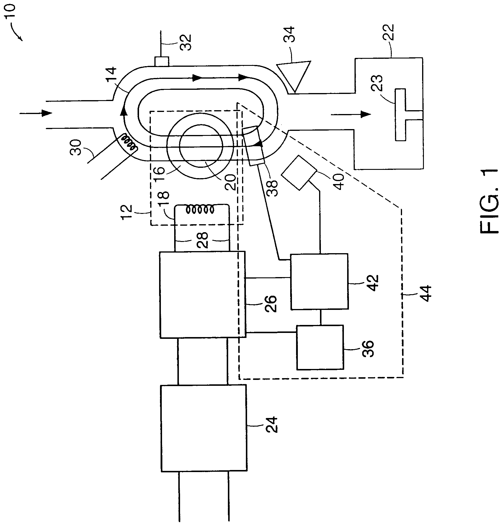
[0039]FIG. 1 is a schematic representation of a toroidal low-field plasma source 10 for producing activated gases that embodies the invention. The source 10 includes a power transformer 12 that couples electromagnetic energy into a plasma 14. The power transformer 12 includes a high permeability magnetic core 16, a primary coil 18, and a plasma chamber 20 which allows the plasma 14 to form a secondary circuit of the transformer 12. The power transformer 12 can include additional magnetic cores and conductor primary coils (not shown) that form additional secondary circuits.

[0040]The plasma chamber 20 may be formed from a metallic material such as aluminum or a refractory metal, or may be formed from a dielectric material such as quartz. One or more sides of the plasma chamber 20 may be exposed to a process chamber 22 to allow charged particles generated by the plasma 14 to be in direct contact with a material to be processed (not shown). A sample holder 23 may be positioned in the pr...


PUM

PropertyMeasurementUnit
pressureaaaaaaaaaa
electric fieldaaaaaaaaaa
voltageaaaaaaaaaa

Abstract

An apparatus for dissociating gases includes a plasma chamber that may be formed from a metallic material and a transformer having a magnetic core surrounding a portion of the plasma chamber and having a primary winding. The apparatus also includes one or more switching semiconductor devices that are directly coupled to a voltage supply and that have an output coupled to the primary winding of the transformer. The one or more switching semiconductor devices drive current in the primary winding that induces a potential inside the chamber that forms a plasma which completes a secondary circuit of the transformer.

Description

[0001]This application is a continuation of U.S. patent application Ser. No. 10 / 143,070, filed on May 10, 2002, which is a continuation of U.S. patent application Ser. No. 09 / 659,881, filed on Sep. 12, 2000, now U.S. Pat. No. 6,486,431, which is a continuation of U.S. patent application Ser. No. 08 / 883,281 filed on Jun. 26, 1997, now U.S. Pat. No. 6,150,628.FIELD OF THE INVENTION[0002]This invention relates generally to the field of generating activated gas containing ions, free radicals, atoms and molecules and to apparatus for and methods of processing materials with activated gas.BACKGROUND OF THE INVENTION[0003]Plasma discharges can be used to excite gases to produce activated gases containing ions, free radicals, atoms and molecules. Activated gases are used for numerous industrial and scientific applications including processing solid materials such as semiconductor wafers, powders, and other gases. The parameters of the plasma and the conditions of the exposure of the plasma ...

Claims


Application Information

Patent Timeline
Patent Type & Authority Patents(United States)
IPC IPC(8): B23K10/00H05H1/46H01J27/16H01J37/32H01L21/205H01L21/302H01L21/3065
CPCH01J27/16H01J37/32009H01J37/32862H01J37/32357H01J37/321
Inventor SMITH, DONALD K.CHEN, XINGHOLBER, WILLIAM M.GEORGELIS, ERIC
Owner MKS INSTR INC
Why Eureka
Try Eureka