Blockless reamer

a technology of reamers and blocks, applied in the field of reamers, can solve problems such as inability to accept shaft failure, and achieve the effects of convenient assembling and disassembly, convenient machine operation, and simple pocket shap

Active Publication Date: 2006-02-21
NAT OILWELL VARCO LP
View PDF4 Cites 11 Cited by
  • Summary
  • Abstract
  • Description
  • Claims
  • Application Information

AI Technical Summary

Benefits of technology

[0006]The use of pins rather than blocks to secure the reamer unit within the pocket causes the reamer tool to be easier to machine due to the fact that no individual pieces besides the tool body are required to be fashioned; and the shape of the pocket is simpler, as it does not need to include features necessary for the insertion of a block. The application of pins further causes the reamer tool to be easier to assemble and take apart. The pin configuration means it is relatively simple to remove reamer units from the body. Thus, worn cutters can be replaced, or pristine reamer units can be removed and refitted into another tool body. Generally the pin is engaged at each end in the tool body and extends across the pocket. In one embodiment, the pins are each engaged to the tool body by insertion into holes drilled through the body, the holes opening into the pocket such that the pins each extend across the pocket. The holes can be formed with a countersink portion to facilitate installation of the pins.

Problems solved by technology

In such an embodiment, the shaft must be sized to accommodate the holes without being compromised to the extent that unacceptable failure of the shaft occurs due to the holes.

Method used


Image

  • Blockless reamer
  • Blockless reamer
  • Blockless reamer

Examples


Embodiment Construction

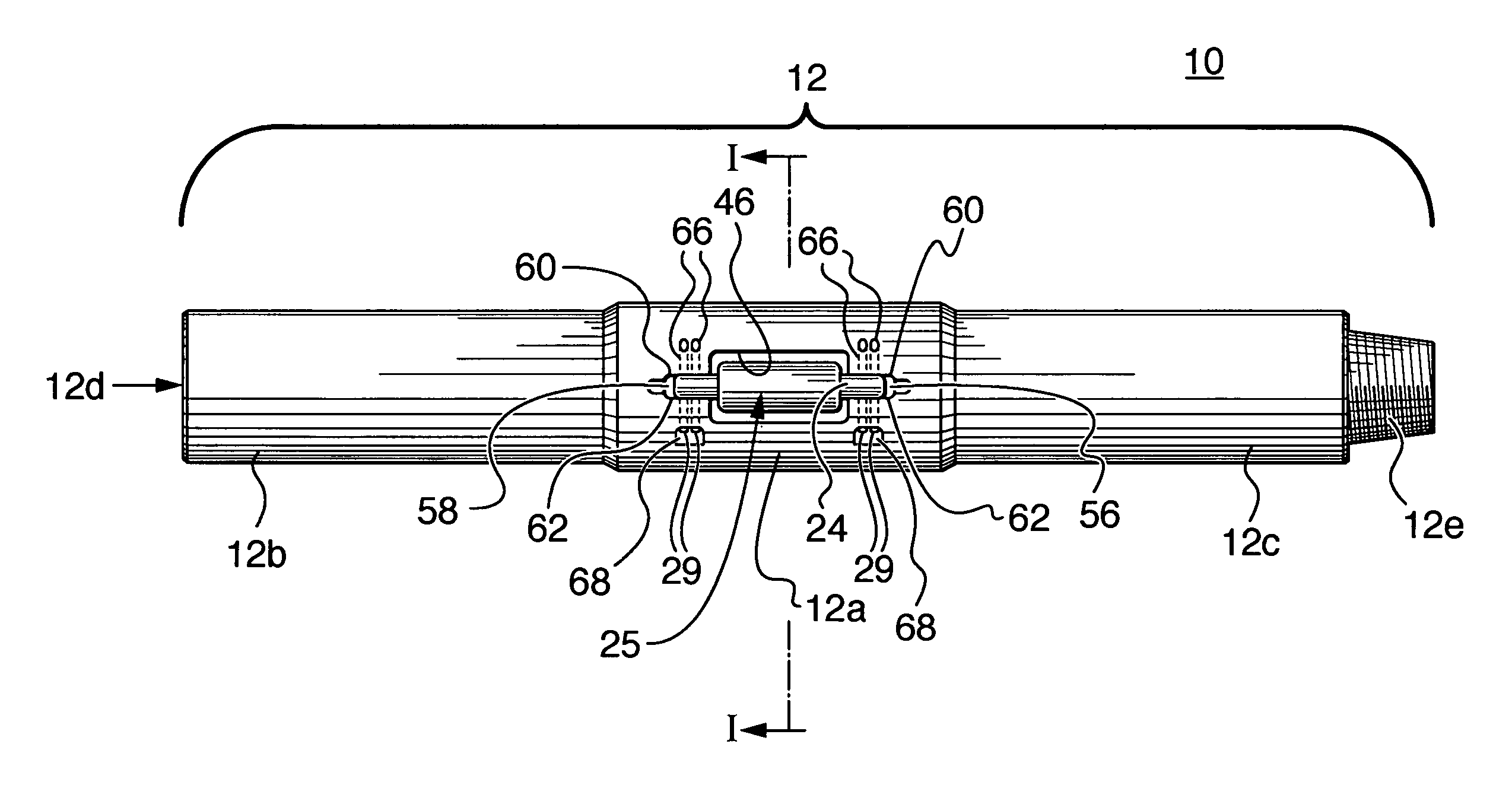
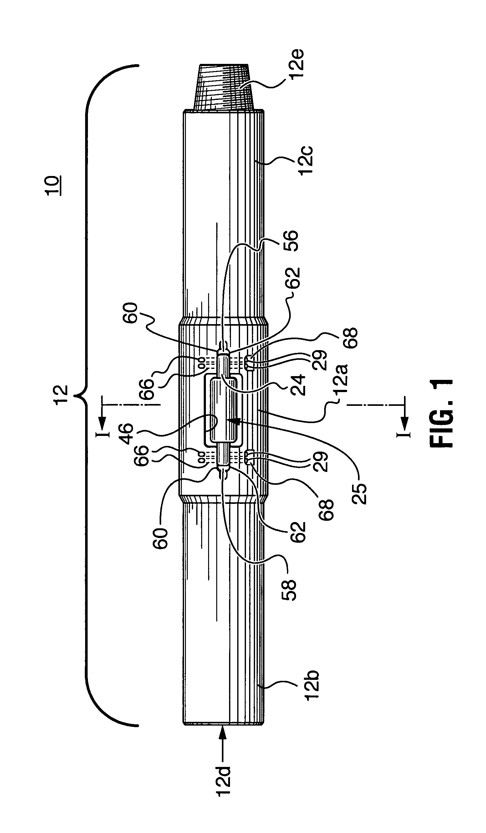
[0020]As shown in FIG. 1, the blockless reamer drilling tool 10 includes a generally cylindrical, elongated body 12 which includes a constant diameter cylindrical section 12a and a reduced diameter upper section 12b and a reduced diameter lower section 12c. The reduced diameter upper section 12b terminates a “box” end portion having a female thread section 12d commonly used in oil well drilling tool designs. The lower reduced diameter section 12c terminates in a “pin” end having external threads 12e to mount the reamer tool in an oil well drill string or other string of pipe for insertion into a bore hole in an oil well or any other bore hole such as a mining bore hole, as shown in FIG. 2. In application, the reamer tool acts to stabilize a bore hole and ensure that the bore hole is drilled to gauge.

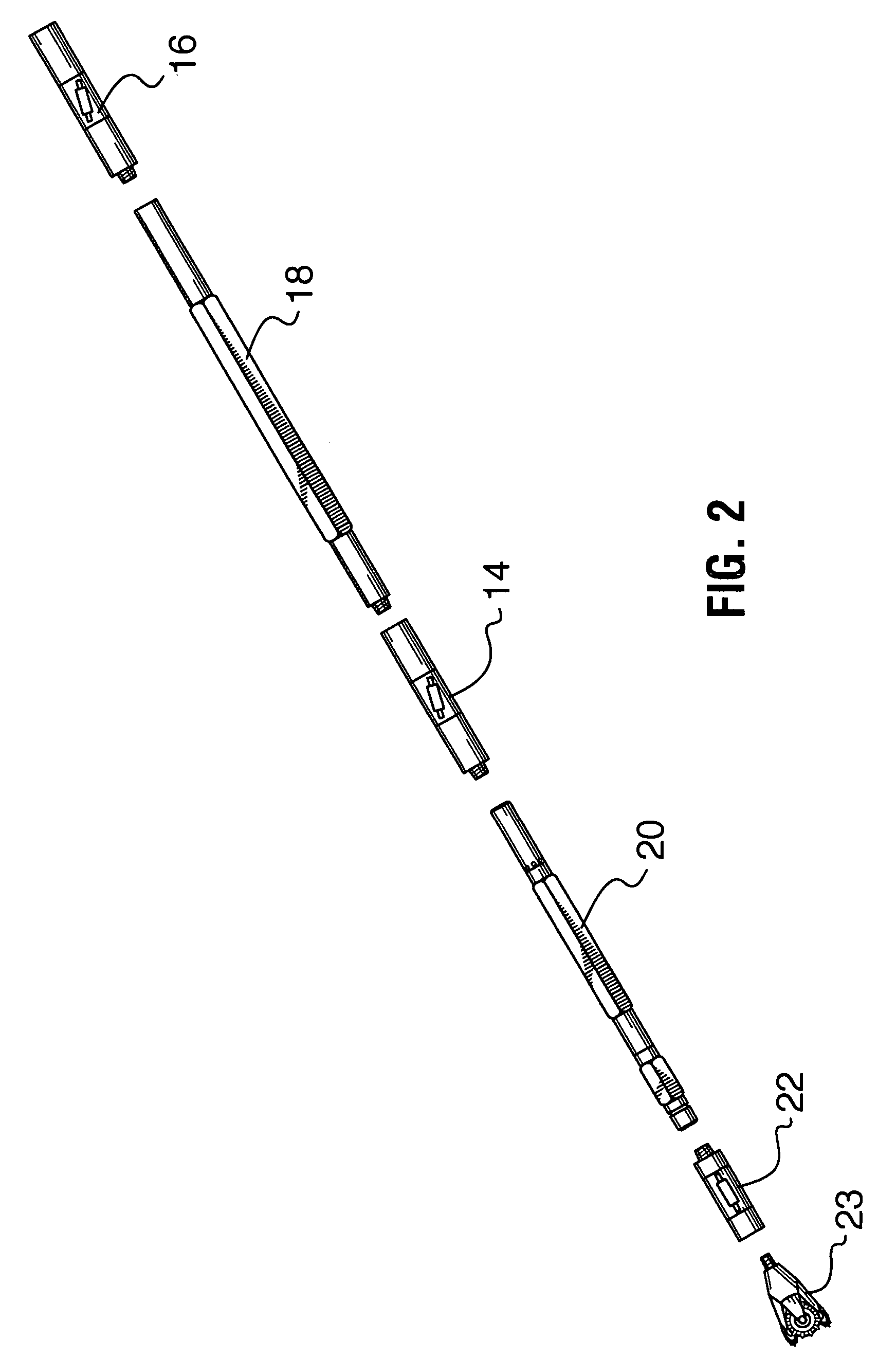
[0021]FIG. 2 shows the integration of multiple blockless reamer drilling tools within a portion of a drill string. In one embodiment of the invention a drill string may be created so tha...


PUM


Abstract

A blockless reamer drilling tool comprising an elongated tool body and a reamer unit. The reamer unit includes, a shaft having a first end and a second end and a cutter mounted on the shaft between the first and second ends. A pocket on the exterior surface of the tool body is sized to accept the reamer unit with a portion of the reamer unit recessed in the pocket. A plurality of pins engage the tool body and secure the reamer unit within the pocket. The plurality of pins includes a first pin engaging the tool body and passing through the shaft at the first end and a second pin engaging the tool body and passing through the shaft at the second end.

Description

BACKGROUND OF INVENTION[0001]This invention relates to reamers and similar tools for enlarging bore holes and, in particular, to blockless reamers.[0002]Reamers for enlarging bore holes drilled for oil wells and mine shafts have been known in the drilling art for many decades. Typically, a reamer includes a central body having three or more roller reamer units mounted at circumferally spaced intervals around the tool body. The reamer tool is mounted in a string of drill pipe, drill collar or other rotatable pipe such that the reamer is rotated with the drill pipe through the well bore in order to enlarge the bore. The roller reamer units rollably engage the well bore wall to enlarge the bore as the drill string moves through the hole. Roller reamers are used to roll against the hole wall of an in-gauge hole to reduce the torque of the drill collars against the hole wall of a directionally drilled hole.[0003]Roller reamer tools have traditionally included means for installing a reame...

Claims


Application Information

Patent Timeline
Patent Type & Authority Patents(United States)
IPC IPC(8): E21B10/30E21B10/28
CPCE21B10/30E21B10/28
Inventor CROOKS, JAY CAMRON ADAM
Owner NAT OILWELL VARCO LP
Why Eureka
Try Eureka