Fuel injection system

a fuel injection system and fuel technology, applied in the direction of electric control, process and machine control, instruments, etc., can solve the problems of reducing fuel cost, affecting fuel flow, and affecting fuel flow, so as to improve fuel efficiency, prevent the effect of drivability and exhaust gas performance degradation caused by the change in fuel viscosity with respect to the standard state, and detect the fuel viscosity

Inactive Publication Date: 2006-03-21
DENSO CORP
View PDF8 Cites 20 Cited by
  • Summary
  • Abstract
  • Description
  • Claims
  • Application Information

AI Technical Summary

Benefits of technology

[0007]In one aspect of the fuel injection system according to the present invention, when there is a difference between the standard state obtained by a standard state estimation means and a cylinder internal pressure or a heat release rate detected by a cylinder internal pressure sensor upon fuel injection, a correction means corrects at least one of an injection start timing, an injection amount, and a supply pressure in a direction to eliminate the difference.
[0020]In this arrangement, because the cetane value (fuel performance) correction in addition to the fuel viscosity correction can be performed, the degradation of drivability and the degradation of exhaust gas performance caused by a change in fuel viscosity with respect to the standard state can be prevented.

Problems solved by technology

This causes degradation of drivability performance, causes difficulty in air-fuel ratio control with high accuracy, and further disturbs techniques for improving fuel cost to the maximum and improving exhaust gas performance to the maximum.

Method used


Image

  • Fuel injection system
  • Fuel injection system
  • Fuel injection system

Examples


embodiment 1

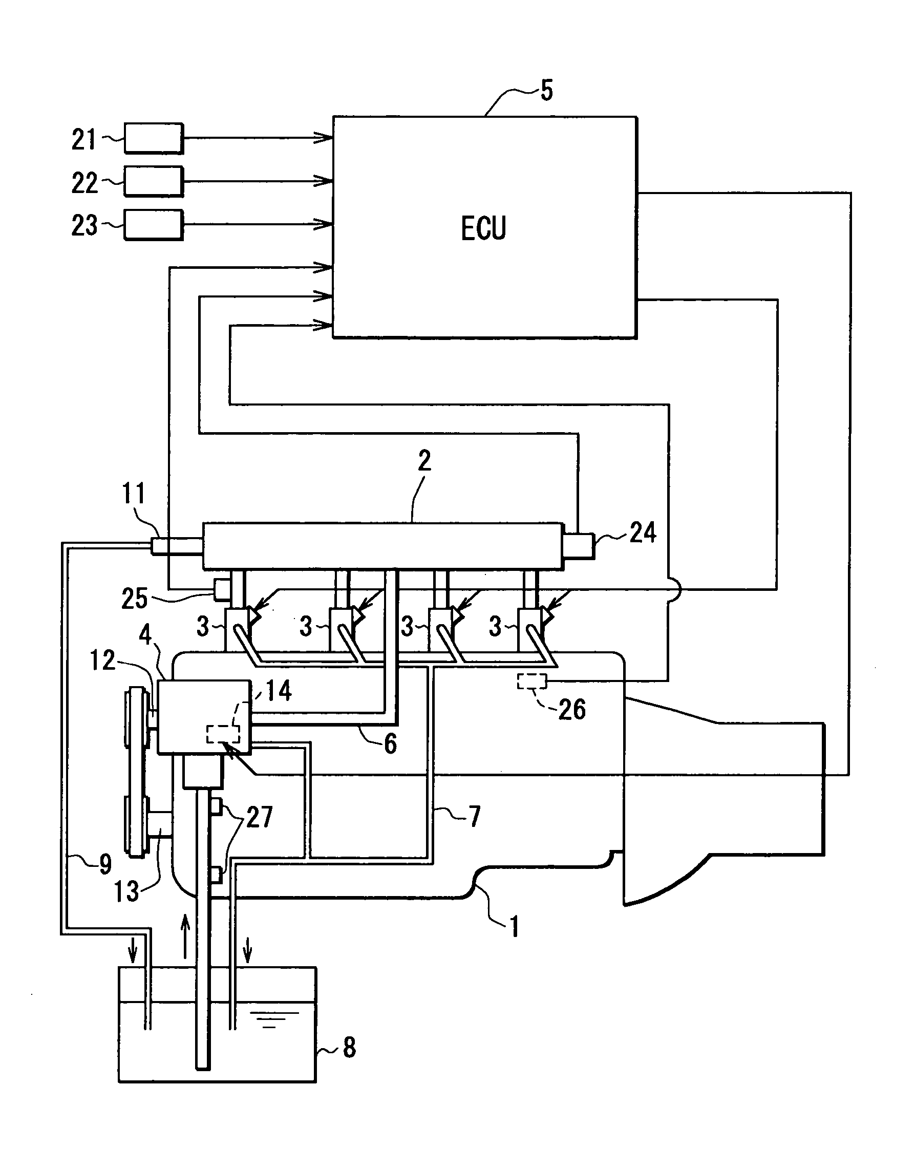
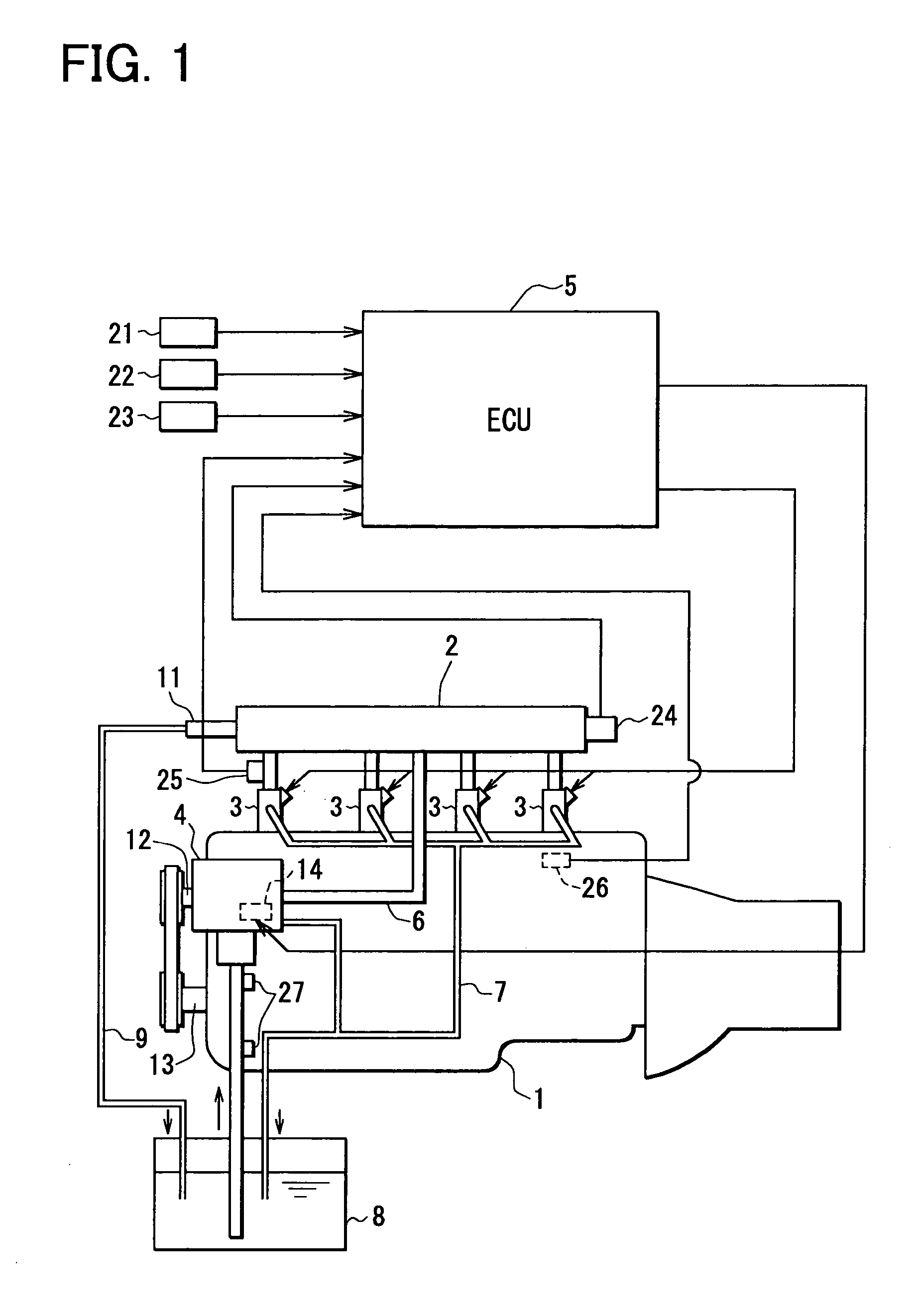
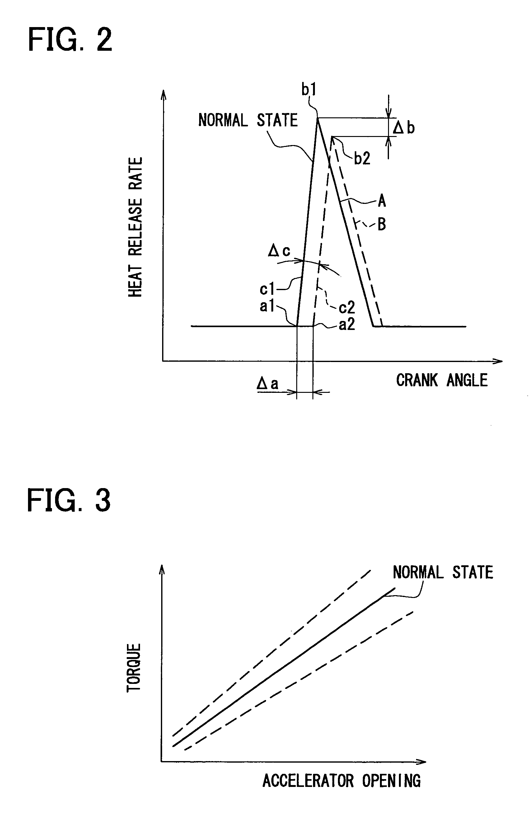
[0054]Accordingly, the function of correction means for comparing the target heat release rate A with the real heat release rate B, and correcting the injector 3 and the SCV 14 based on the difference so as to bring the target heat release rate A and the real heat release rate B into correspondence, is programmed in the ECU 5 of this

[0055]The common rail fuel injection system has a cylinder internal pressure sensor 26 to detect a cylinder internal pressure of the engine 1. The cylinder internal pressure sensor 26 of this embodiment 1 has an approximate grow-plug shape. A sensor portion arranged at its end, inserted into each combustion chamber of the engine 1, directly detects each cylinder internal pressure. Note that the cylinder internal pressure sensor 26 may be provided in all the cylinders or in any one of the cylinder.

[0056]The ECU 5 is provided with standard state estimation means (program) for obtaining the target heat release rate A (standard state) upon fuel injection, an...

second embodiment

[0073]Accordingly, in the common rail fuel injection system of the second embodiment, the injection amount is corrected in correspondence with change in fuel viscosity. The system has viscosity detection means for detecting a fuel viscosity N of fuel supplied to the injector 3, and viscosity correction means (program) for correcting the injection amount Q based on the fuel viscosity N detected by the viscosity detection means.

[0074]When the fuel viscosity N detected by the viscosity detection means is higher than a standard viscosity N0 (N>N0), the viscosity correction means performs correction to increase the injection amount Q (more particularly, correction to increase a valve opening period in the injector 3) as the difference (N−N0) from the standard viscosity increases. The computation is obtained from a map or expression.

[0075]In this arrangement, as the fuel viscosity N increases and the fuel does not flow easily, the correction to increase the injection amount Q is performed...

embodiment 2

[0083]In the common rail fuel injection system of the embodiment 2, the standard viscosity N0 is compared with the fuel viscosity N of fuel supplied to the injector 3, and when there is a difference between the viscosities, the injection amount Q is corrected in accordance with the difference. Even when the fuel viscosity N has changed with respect to the standard viscosity N0, an optimum injection amount corresponding to a vehicle running state can be realized. Accordingly, the degradation of drivability performance and the degradation of exhaust gas performance caused by the change of the fuel viscosity N with respect to the standard viscosity N0 can be prevented.

[0084]Note that in the embodiment 2, when the fuel viscosity N detected by the viscosity detection means is higher than the standard viscosity N0 (N>N0), the correction to increase the injection amount Q is performed as the difference (N−N0) increases, on the other hand, when the fuel viscosity N detected by the viscosity...


PUM


Abstract

A fuel injection system includes an injector, a controller, and a cylinder internal pressure sensor. The injector injects fuel to an engine. The controller controls injection start timing of the injector, an injection amount, and a supply pressure of the injected fuel. The cylinder internal pressure sensor detects one of a cylinder internal pressure and a heat release rate of the internal combustion engine. The controller has a standard estimator and a corrector. The standard state estimator obtains a standard state of one of the cylinder internal pressure and the heat release rate upon fuel injection from the injector. The corrector corrects at least one of the injection start timing, the injection amount, and the supply pressure in a direction to eliminate a difference that exists between the standard state obtained by the standard state estimator and one of the cylinder internal pressure and the heat release rate detected by the cylinder internal pressure sensor.

Description

CROSS REFERENCE TO RELATED APPLICATIONS[0001]This application is based upon and claims the benefit of priority of Japanese Patent Application No. 2004-137702, filed on May 6, 2004, the contents of which are incorporated herein by reference.FIELD OF THE INVENTION[0002]The present invention relates to a fuel injection system for an internal combustion engine and, more particularly, to a system for performing correction control of injection amount in accordance with fuel viscosity.BACKGROUND OF THE INVENTION[0003]A conventional controller of a fuel injection system calculates an optimum injection amount and an injection start timing and the like from various engine-related parameters. The, the fuel injection system supplies fuel to the engine by the injection amount obtained from the computation by drive-controlling the injector.[0004]However, even if the accuracy of parts such as the injector is improved to the maximum, when the viscosity of the fuel supplied to the injector and / or fu...

Claims


Application Information

Patent Timeline
Patent Type & Authority Patents(United States)
IPC IPC(8): F02M7/28F02D45/00F02D35/02F02D41/14F02D41/38F02D41/40
CPCF02D35/023F02D41/3836F02D41/401Y02T10/44F02D2200/0606F02D2200/0612G01N11/02F02D2200/0602Y02T10/40
Inventor NAGAI, KOICHISUENAGA, RYO
Owner DENSO CORP
Why Eureka
Try Eureka