AI technical title is built by Patsnap AI team. It summarizes the technical point description of the patent document.
a terminal and female technology, applied in the direction of electrically conductive connections, coupling device connections, electrical apparatus, etc., can solve the problems of effective dampening of vibration, reducing transition resistance, and effectively dampening of transversal direction of action of contact tabs, so as to facilitate insertion and more accurate manner
Active Publication Date: 2006-03-21
YAZAKI EURO
View PDF14 Cites 26 Cited by
Summary
Abstract
Description
Claims
Application Information
AI Technical Summary
This helps you quickly interpret patents by identifying the three key elements:
Problems solved by technology
Method used
Benefits of technology
Benefits of technology
[0008]Advantageous in this embodiment is, that the terminal tab, which is accommodated in the female terminal, is elastically acted upon by the contact tabs as well as by the locking tabs, so that a secure retainment is achieved. Furthermore, vibrations, produced transversally to the direction of action of the contact tabs are effectively dampened. Such vibrations can cause frictional corrosion or wear, respectively, at the contact zones, whereby the transition resistance is immensely reduced.
[0016]To be able to allow an insertion in a more accurate manner, it is provided, that the contact tabs terminate in front of an insertion opening of the support element and that the support element form by means of wall portions of the two walls covering the contact tabs, which wall portions are inverted towards the inside and towards the free ends of the contact tabs, guiding faces for a terminal tab to be inserted. Thus, it is prevented, that the terminal tab can accidentally get under the contact tabs.
Problems solved by technology
Furthermore, vibrations, produced transversally to the direction of action of the contact tabs are effectively dampened.
Such vibrations can cause frictional corrosion or wear, respectively, at the contact zones, whereby the transition resistance is immensely reduced.
Method used
Image
Click on the blue label to locate the original text in one second.
Reading with bidirectional positioning of images and text.
Examples
first embodiment
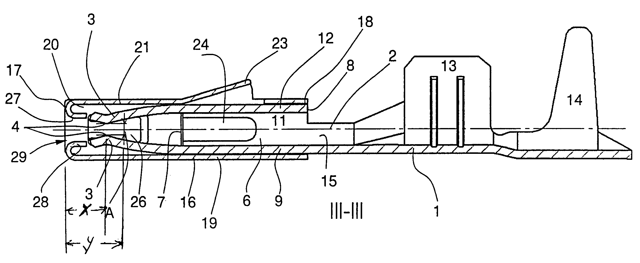
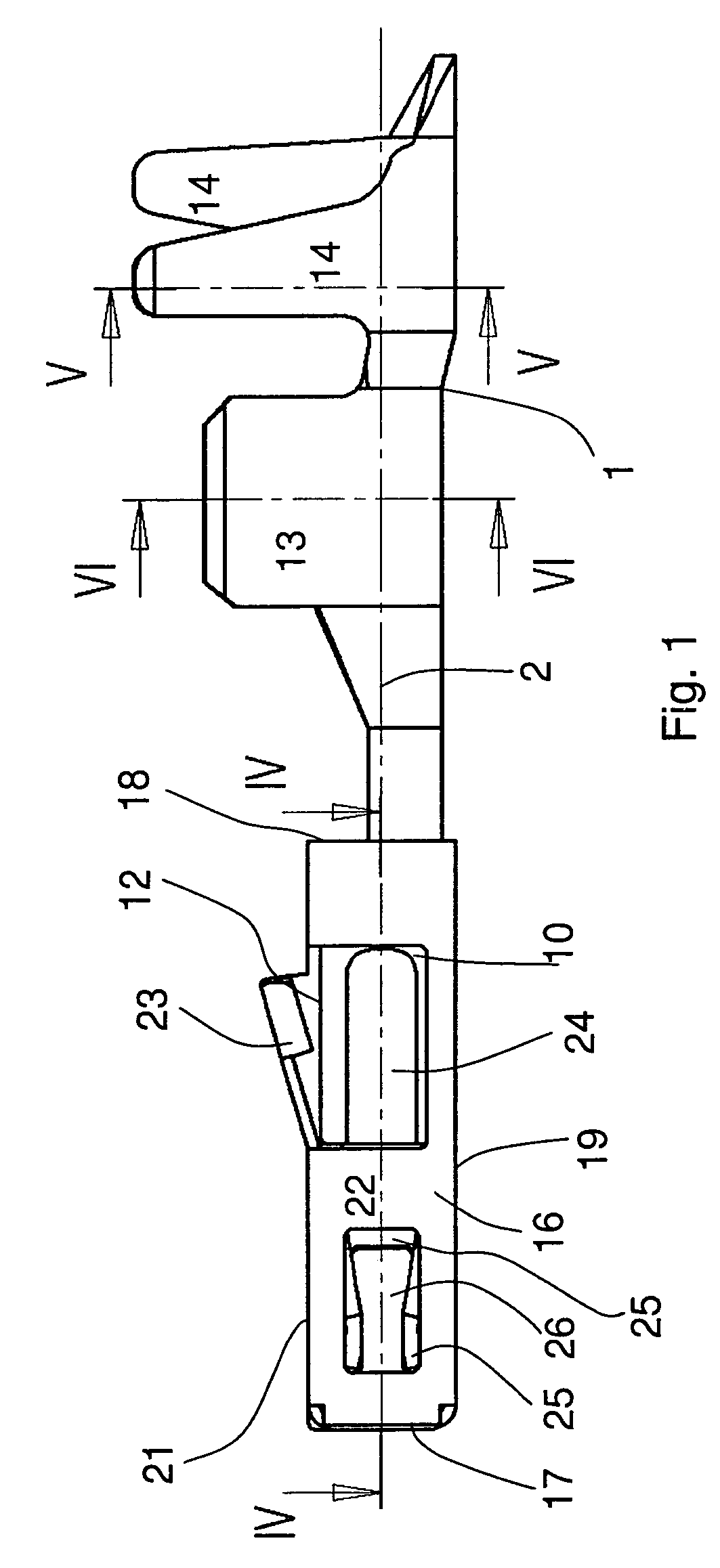
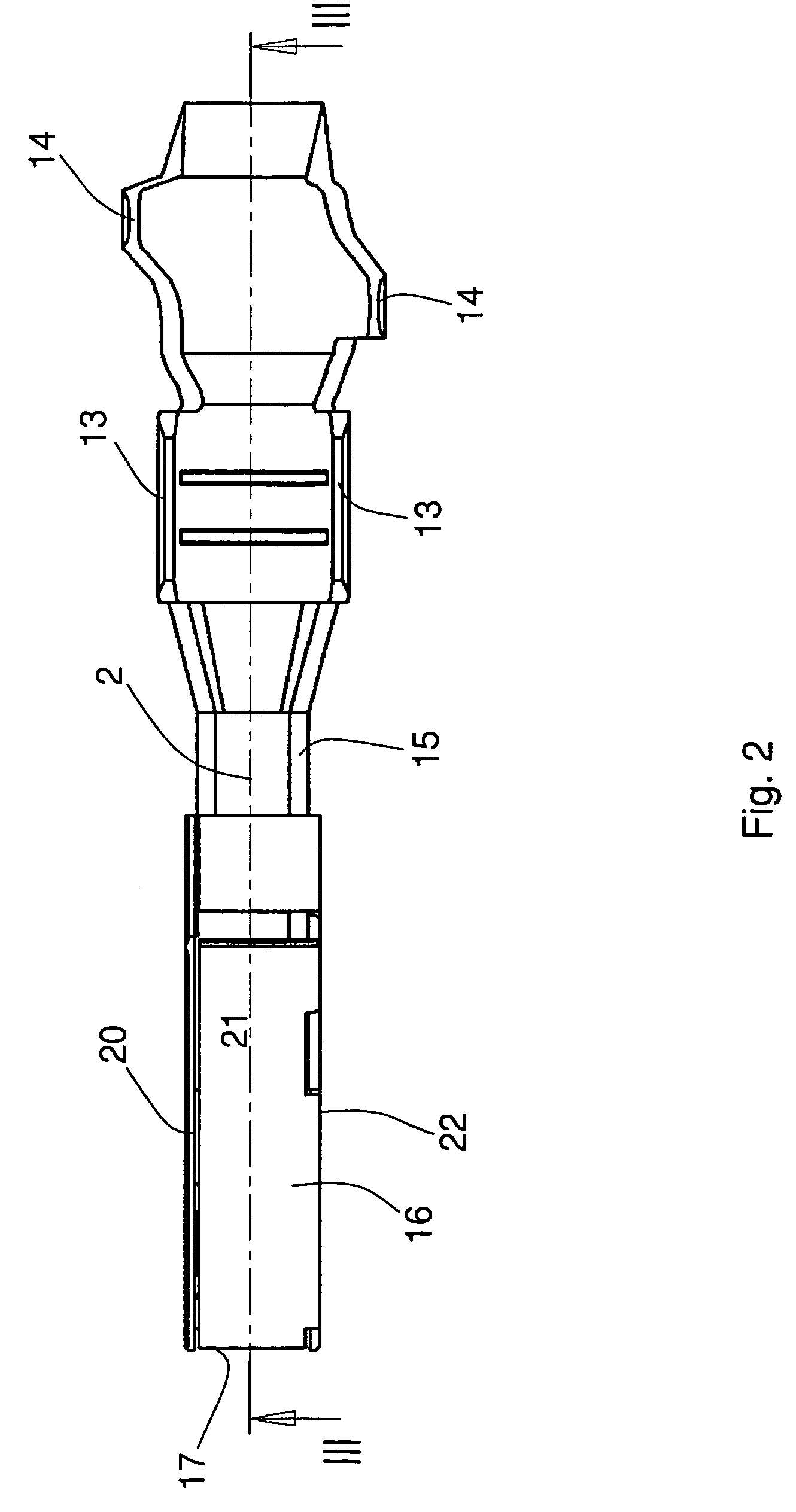
[0029]The following is a description of the invention with reference to FIGS. 1 to 6.
[0030]The female terminal according to this embodiment comprises a contact element 1, forming the longitudinal axis 2, which also represents the longitudinal axis of the whole female terminal. The contact element 1 comprises a base portion 6, having a first end 7 and a second end 8 and formed box-like in cross-section, i.e. forming a rectangular hollow profile, having the side walls 9, 10, 11, 12. The two side walls 9 and 12 form a pair and are arranged opposed to each other. The two side walls 10, 11 form also a pair and are arranged opposed to each other but are arranged perpendicular to the two other sidewalls 9, 12. Contact tabs 3, which with increasing distance from the first end 7 approach each other and form before their free ends contact zones 4 facing each other, project from the first end 7 of the two opposed side walls 9, 12. Starting from the contact zones 4 and continuing in a direction...
second embodiment
[0036]In the second embodiment shown in FIG. 7 the contact element 101 is reduced to the contact tabs 103, connected to each other, with the contact zones 104. These are accommodated in a support element 116, holding the contact element 101. The essential difference to the embodiment of FIGS. 1 to 6 is, that the crimping tabs 113 and 114 are not connected to the contact element 101, but are connected to the support element 116, i.e. are formed integrally with this. In the following the description for the embodiment of FIGS. 1 to 6 is valid analogically for the embodiment of FIG. 7, wherein, however, in the embodiment of FIG. 7 reference numerals are used, which, compared to those of the embodiment of FIGS. 1 to 6, are increased by the numerical value 100. Concerning their description it is referred to the description of FIGS. 1 to 6.
PUM
Abstract
A female terminal for receiving a flat male terminal with a terminal tab (5), having a rectangular cross-section and a predetermined width (B) and thickness (D). The female terminal includes a contact element (1, 101) having two elastic contact tabs (3, 103) approaching each other along a longitudinal axis (2, 102), the contact tabs opposing contact zones (4, 104) for contacting the terminal tab (5); a hollow, rectangular support element (16, 116) defined by four walls (19, 20, 21, 22; 119, 120, 121, 122), enclosing the contact element (1, 101) and in which the elastic contact tabs (3, 103) are accommodated; and a device (13, 113) for electrically connecting a conductor. A first pair of opposing walls (19, 21; 119, 121) cover the contact tabs (3, 103) and a second pair of opposing walls (20, 22; 120, 122) have an elastic locking tab (26, 126) connected thereto. The elastic locking tabs (26, 126) engage between the elastic contact tabs (3, 103) and hold the contact zones (4, 104) of the contact tabs in a pre-tensioned and contact free manner at a distance (A) from each other, which is smaller than the thickness (D) of the terminal tab (5), in a condition in which the flat male terminal is not inserted. The locking tabs (26, 126) have a free distance (C) therebetween before the insertion of the terminal tab (5), which is smaller than the width (B) of the terminal tab (5) and the locking tabs (26, 126) contact the terminal tab (5) in the inserted position along the longitudinal axis (2, 102) in a contact area which is off-set further from the first end (17, 117) of the support element (16, 116) than the contact zones (4, 104) of the contact tabs (3, 103).
Description
BACKGROUND OF THE INVENTION[0001]The invention relates to a female terminal for a flat male terminal with a terminal tab, having a rectangular cross-section.[0002]DE 297 19 153 U1 describes a female terminal for a flat male terminal with a terminal tab, having a rectangular cross-section with a predetermined width and thickness. The female terminal comprises a contact element, forming a longitudinal axis. The contact element has two elastic contact tabs, which approach each other along the longitudinal axis and have, respectively, a contact zone, serving to contact the terminal tab in a clamped manner between each other. The contact zones are arranged opposed to each other. The female terminal comprises further a support element, formed tubular and delimited by walls, enclosing the contact element. In the support element the elastic contact tabs are accommodated. The contact tabs are acted upon by support tabs. The support element has on two opposed walls, respectively, a locking ta...
Claims
Application Information
Patent Timeline
Application Date:The date an application was filed.
Publication Date:The date a patent or application was officially published.
First Publication Date:The earliest publication date of a patent with the same application number.
Issue Date:Publication date of the patent grant document.
PCT Entry Date:The Entry date of PCT National Phase.
Estimated Expiry Date:The statutory expiry date of a patent right according to the Patent Law, and it is the longest term of protection that the patent right can achieve without the termination of the patent right due to other reasons(Term extension factor has been taken into account ).
Invalid Date:Actual expiry date is based on effective date or publication date of legal transaction data of invalid patent.

