Engine-mount

a technology of engine and mounting bracket, which is applied in the direction of shock absorber, jet propulsion mounting, transportation and packaging, etc., can solve the problems of structural vibration, and achieve the effect of dampening the vibration of air in the tire more efficiently

Inactive Publication Date: 2015-12-29
HYUNDAI MOTOR CO LTD
View PDF9 Cites 2 Cited by
  • Summary
  • Abstract
  • Description
  • Claims
  • Application Information

AI Technical Summary

Benefits of technology

[0014]The present invention has been made in an effort to solve the above-described problems associated with the prior art. Various aspects of the present invention provide for an engine mount, in which a band region width of the vibration frequency that can be dampened exhibits more widely and the vibration induced from the air vibration of a tire can be dampened more efficiently.
[0019]A membrane that is vibrated in accordance with the flow of the hydro liquid may be arranged on the nozzle plate to dampen more effectively the vibration produced over a specific frequency region, for example, an idle region.

Problems solved by technology

Generally, vibrations are produced structurally in an engine for a vehicle and are produced also due to an uneven road surface while a vehicle drives.

Method used


Image

  • Engine-mount
  • Engine-mount
  • Engine-mount

Examples


Embodiment Construction

[0027]Reference will now be made in detail to various embodiments of the present invention(s), examples of which are illustrated in the accompanying drawings and described below. While the invention(s) will be described in conjunction with exemplary embodiments, it will be understood that present description is not intended to limit the invention(s) to those exemplary embodiments. On the contrary, the invention(s) is / are intended to cover not only the exemplary embodiments, but also various alternatives, modifications, equivalents and other embodiments, which may be included within the spirit and scope of the invention as defined by the appended claims.

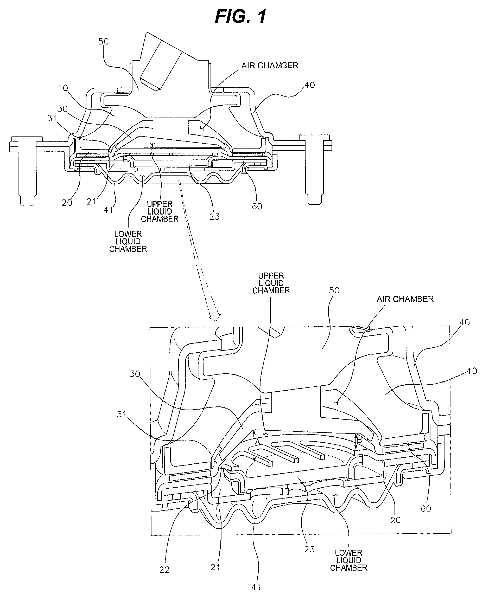
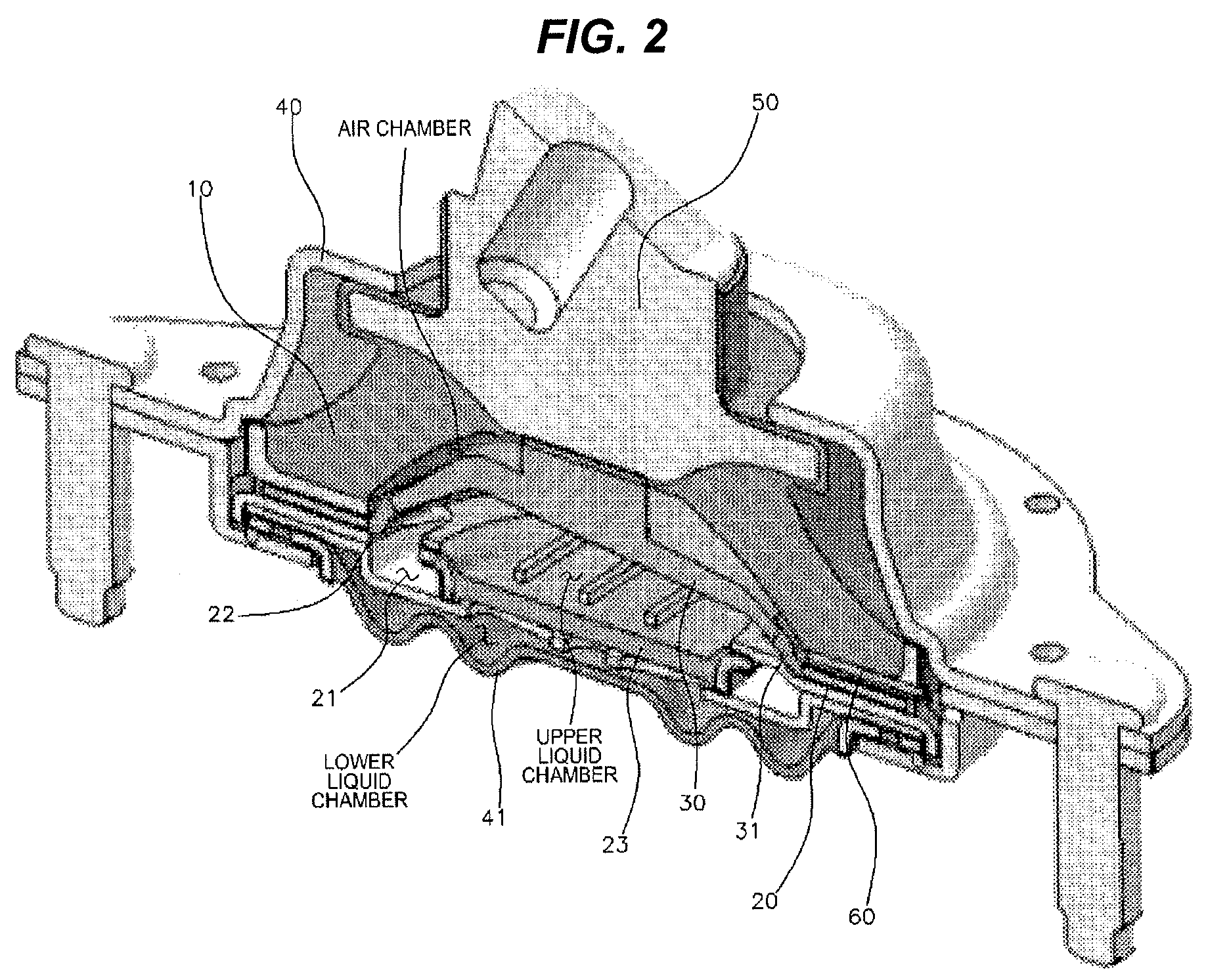
[0028]An engine mount according to the present invention is configured such that a housing 40 is fixed to a vehicle body with bolts and an engine is mounted on a core 50 that protrudes to an upper end of the housing 40 to support weight of the engine wherein the vibration transferred from the engine in accordance with the flow of air ...


PUM


Abstract

An engine mount includes: an insulator arranged inside a housing and deformed elastically in accordance with a force applied to a core connected to an upper end thereof; a nozzle plate having a flow channel opened up / downward for hydro liquid and connected between a diaphragm connected to the housing and the insulator; and a piston partitioning an internal space between the insulator and the nozzle plate and connected to the core to move in accordance force applied to the core, wherein upper and lower liquid chambers are formed between the piston and the nozzle plate, and between the nozzle plate and the diaphragm, respectively, and an air chamber through which ambient air can enter / exit is formed between the piston and the insulator. Vibration produced over a wide frequency region can be dampened more effectively by using air and the hydro liquid as an operation liquid.

Description

CROSS-REFERENCE TO RELATED APPLICATION[0001]The present application claims priority of Korean Patent Application Number 10-2013-0081960 filed Jul. 12, 2013, the entire contents of which application is incorporated herein for all purposes by this reference.BACKGROUND OF INVENTION[0002]1. Field of Invention[0003]The present disclosure relates to an engine-mount, and more particularly, to an engine mount provided with all of properties of an pneumatic mount and a hydro mount (liquid enveloped-type mount).[0004]2. Description of Related Art[0005]Generally, vibrations are produced structurally in an engine for a vehicle and are produced also due to an uneven road surface while a vehicle drives.[0006]The vibrations are produced not due to only one factor but due to several factors and thus the vibrations are produced up-downward, left-rightward and front / rearward.[0007]Furthermore, an engine for a vehicle is not separated from a vehicle body but is connected to a shift device and an air c...

Claims


Application Information

Patent Timeline
Patent Type & Authority Patents(United States)
IPC IPC(8): F16F5/00F16F13/10F16F13/20
CPCF16F13/20F16F13/10B60K5/12F16F15/022F16F15/0232F16F13/06F16F15/02
Inventor KIM, SEUNG-WON
Owner HYUNDAI MOTOR CO LTD
Why Eureka
Try Eureka