Flanged sleeve guide

a sleeve guide and sleeve technology, applied in the direction of machines/engines, liquid fuel engines, applications, etc., can solve the problems of high cost, difficult assembly, and inaccurate machining techniques, and achieve accurate control of the amount of axial movement and the effect of accurate control of the axial movemen

Inactive Publication Date: 2007-11-27
EMERSON CLIMATE TECH INC
View PDF22 Cites 17 Cited by
  • Summary
  • Abstract
  • Description
  • Claims
  • Application Information

AI Technical Summary

Benefits of technology

[0005]The concept of a scroll-type machine has thus been known for some time and has been recognized as having distinct advantages. For example, scroll machines have high isentropic and volumetric efficiency, and, hence, are relatively small and lightweight for a given capacity. They are quieter and more vibration free than many machines because they do not use large reciprocating parts (e.g., pistons, connecting rods, etc.); and because all fluid flow is in one direction with simultaneous compression in plural opposed pockets, there are less pressure-created vibrations. Such machines also tend to have high reliability and durability because of the relatively few moving parts utilized and the relatively low velocity of movement between the scrolls. Scroll machines which have radial compliance to allow flank leakage have an inherent forgiveness to fluid contamination.
[0012]The present invention provides the art with a sleeve guide which is designed to work in conjunction with another component of the scroll machine to accurately control the axial movement of the non-orbiting scroll member. The sleeve guide preferably works in conjunction with the partition to accurately control the amount of axial movement as well as provide a positive stop for the non-orbiting scroll member since the partition is secured to the shell of the compressor.

Problems solved by technology

One of the difficult areas of design in a scroll-type machine concerns the technique used to achieve tip sealing under all operating conditions, and also during all speeds in a variable speed machine.
Conventionally, this has been accomplished by (1) using extremely accurate and very expensive machining techniques, (2) providing the wrap tips with spiral tip seals, which, unfortunately, are hard to assemble and often unreliable, or (3) applying an axially restoring force by axial biasing the orbiting scroll or the non-orbiting scroll towards the opposing scroll using compressed working fluid.
The latter technique has some advantages but also presents problems.
The combination of using a bolt with a sleeve guide and all of the tolerance stack-ups associated with this design do not permit the tighter control over the amount of axial travel without adding additional costs for the manufacture of the scroll machine.

Method used


Image

  • Flanged sleeve guide
  • Flanged sleeve guide
  • Flanged sleeve guide

Examples


Embodiment Construction

[0019]The following description of the preferred embodiment(s) is merely exemplary in nature and is in no way intended to limit the invention, its application, or uses.

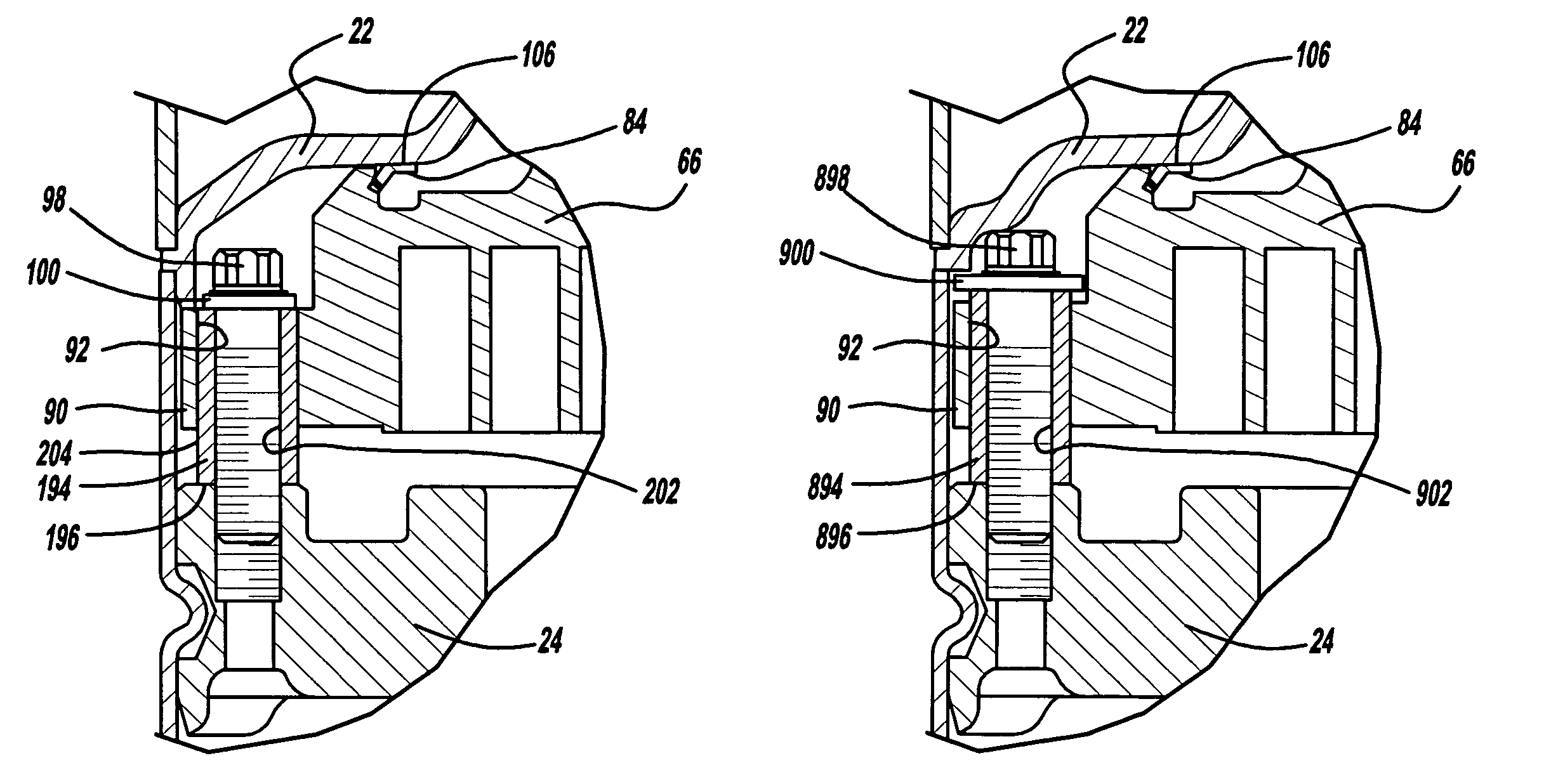
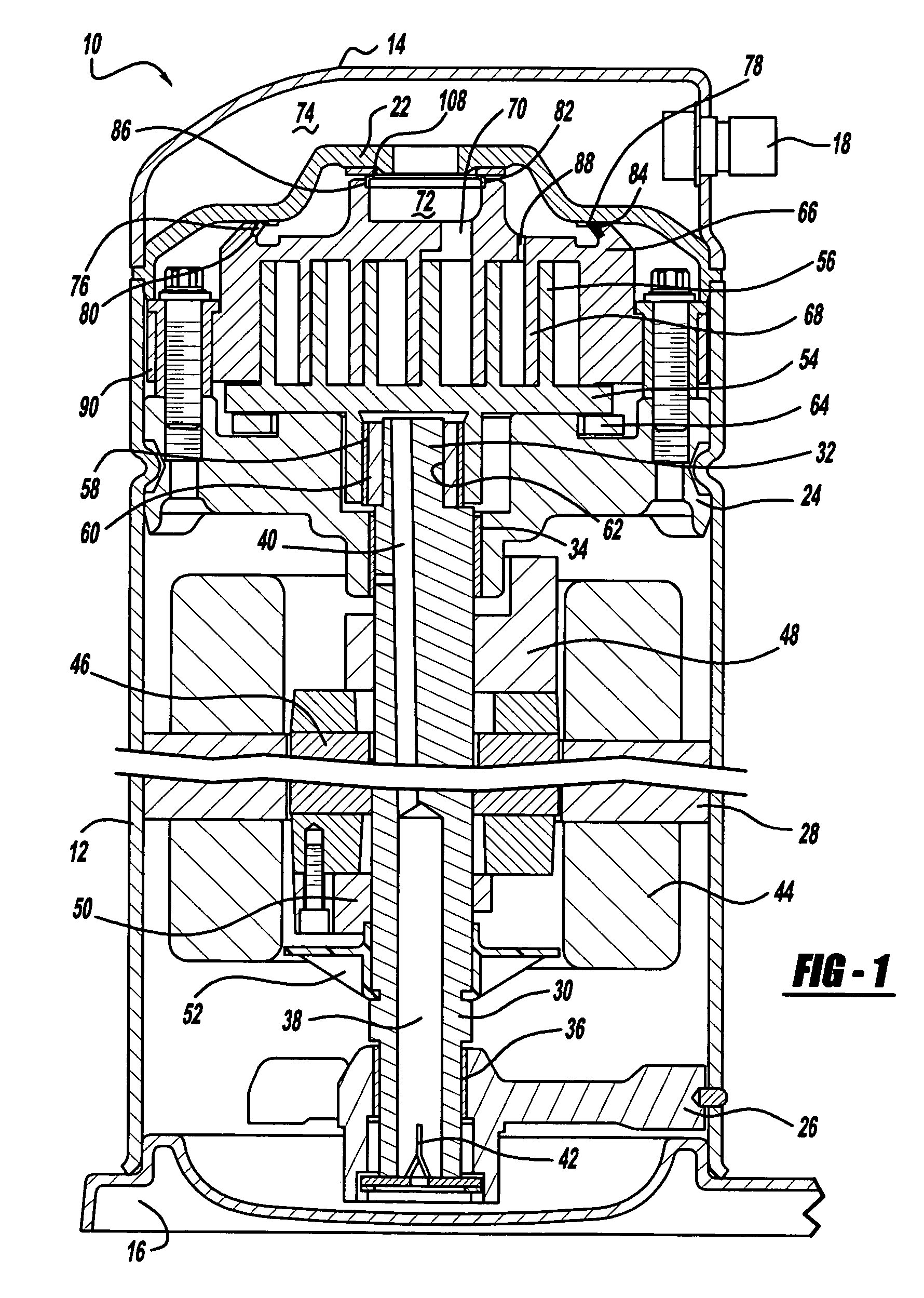
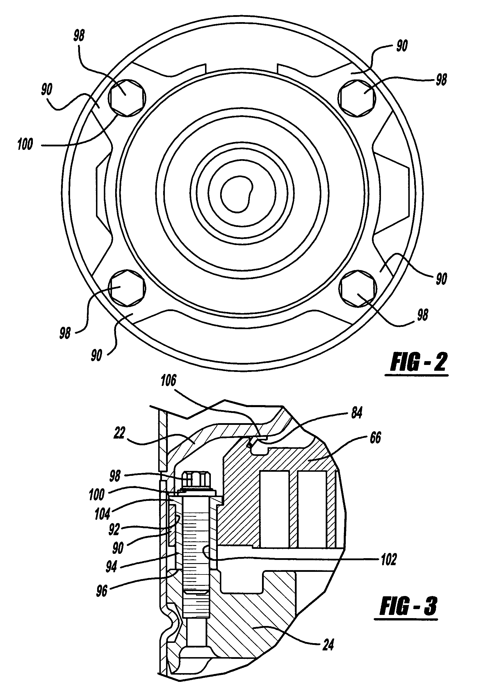
[0020]There is illustrated in FIG. 1 a scroll compressor which incorporates a non-orbiting scroll mounting arrangement in accordance with the present invention and which is designated generally by reference numeral 10. Compressor 10 comprises a generally cylindrical hermetic shell 12 having welded at the upper end thereof a cap 14 and at the lower end thereof a base 16 having a plurality of mounting feet (not shown) integrally formed therewith. Cap 14 is provided with a refrigerant discharge fitting 18 which may have the usual discharge valve therein (not shown). Other major elements affixed to the shell include a transversely extending partition 22 which is welded about its periphery at the same point that cap 14 is welded to shell 12, a stationary main bearing housing or body 24 which is suitably secured to shell 12...


PUM


Abstract

A scroll machine includes a shell and a pair of scroll members. At least one of the scroll members disposed in the shell is mounted for axial movement with respect to the other scroll member disposed in the scroll. The amount of axial movement of at least one scroll member is accurately controlled by providing a stop. The stop is defined by the contact of the end plate of the at least one scroll member with another member of the scroll machine which is accurately positioned within the shell of the scroll machine. The member can be either the shell or another component which engages the shell.

Description

FIELD OF THE INVENTION[0001]The present invention relates to mounting arrangements for the scroll member of a scroll machine. More particularly, the present invention relates to a flanged sleeve guide used for mounting one of the scroll members having axial compliance.BACKGROUND AND SUMMARY OF THE INVENTION[0002]A class of machines exists in the art generally known as “scroll” machines for the displacement of various types of fluids. Such machines may be configured as an expander, a displacement engine, a pump, a compressor, etc., and the features of the present invention are applicable to any one of these machines. For purposes of illustration, however, the disclosed embodiments are in the form of a hermetic refrigerant compressor.[0003]Generally speaking, a scroll machine comprises two spiral scroll wraps of similar configuration, each mounted on a separate end plate to define a scroll member. The two scroll members are interfitted together with one of the scroll wraps being rotat...

Claims


Application Information

Patent Timeline
Patent Type & Authority Patents(United States)
IPC IPC(8): F04C18/00
CPCF04C27/005F04C18/0215A01G9/02A01G27/005A01G27/008A01G27/02A47G7/041B44C5/06B44C5/08
Inventor STOVER, CHRISTOPHER
Owner EMERSON CLIMATE TECH INC
Why Eureka
Try Eureka