Ink-jet recording head having a vibration plate prevented from being damaged and ink-jet recording apparatus for using the same

a technology of inkjet recording and vibration plate, which is applied in the field can solve the problems of inkjet recording head involvement, difficulty in jet recording head involvement, and complicated manufacturing process, and achieve the effect of enhancing durability

Inactive Publication Date: 2005-03-22
SEIKO EPSON CORP
View PDF14 Cites 23 Cited by
  • Summary
  • Abstract
  • Description
  • Claims
  • Application Information

AI Technical Summary

Benefits of technology

In the twenty-first aspect, an ink-jet recording head wi...

Problems solved by technology

On the contrary, a difficult process, in which the piezoelectric element is cut and divided into a comb teeth shape to make it coincide with an array pitch of the nozzle orifice, and an operation of positioning and fixing the cut and divided piezoelectric element onto the pressure generating chamber are required for the former ink-jet recording head, thus there is a problem of a complicated manufacturing process.
However, the latter ink-jet recording head has been involved in a problem of difficulty in a high density array of the pressure generating chambers...

Method used


Image

  • Ink-jet recording head having a vibration plate prevented from being damaged and ink-jet recording apparatus for using the same
  • Ink-jet recording head having a vibration plate prevented from being damaged and ink-jet recording apparatus for using the same
  • Ink-jet recording head having a vibration plate prevented from being damaged and ink-jet recording apparatus for using the same

Examples


embodiment 1

(Embodiment 1)

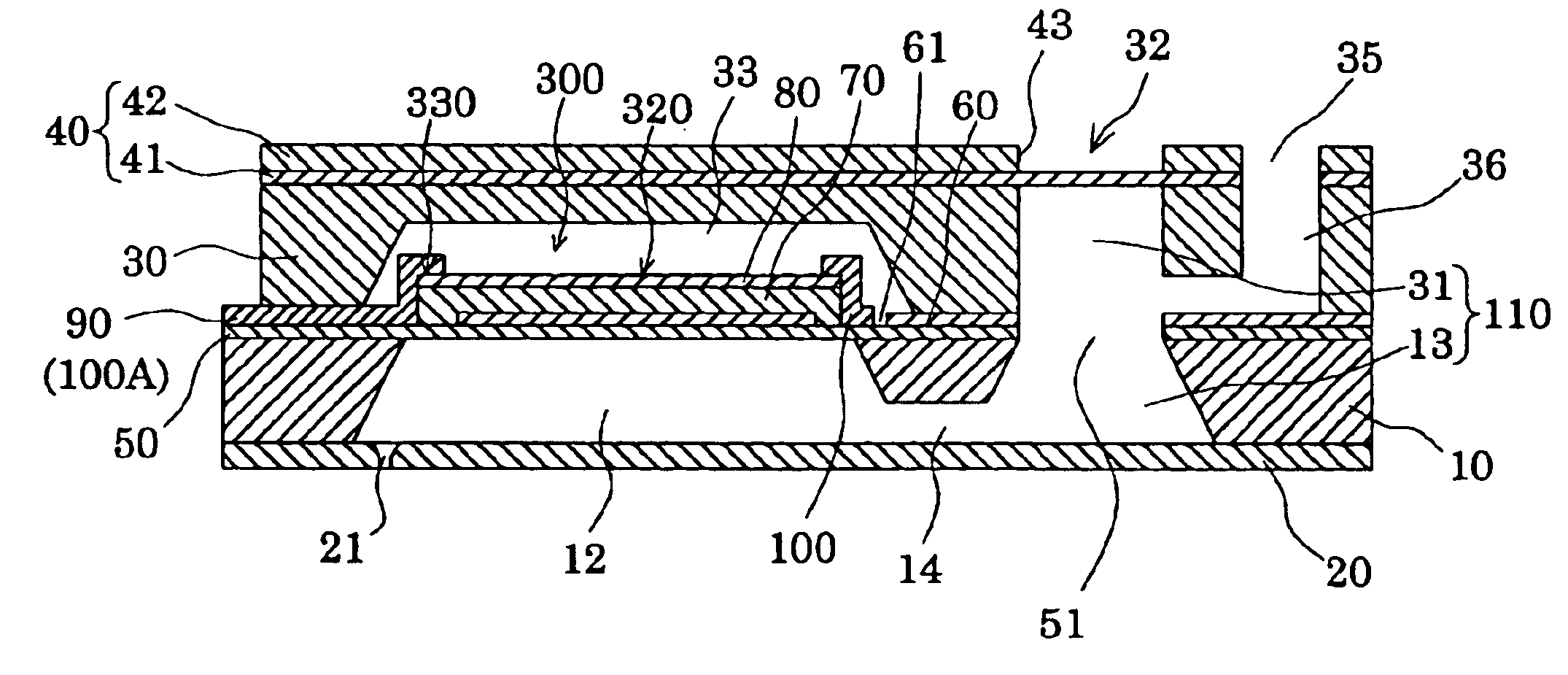
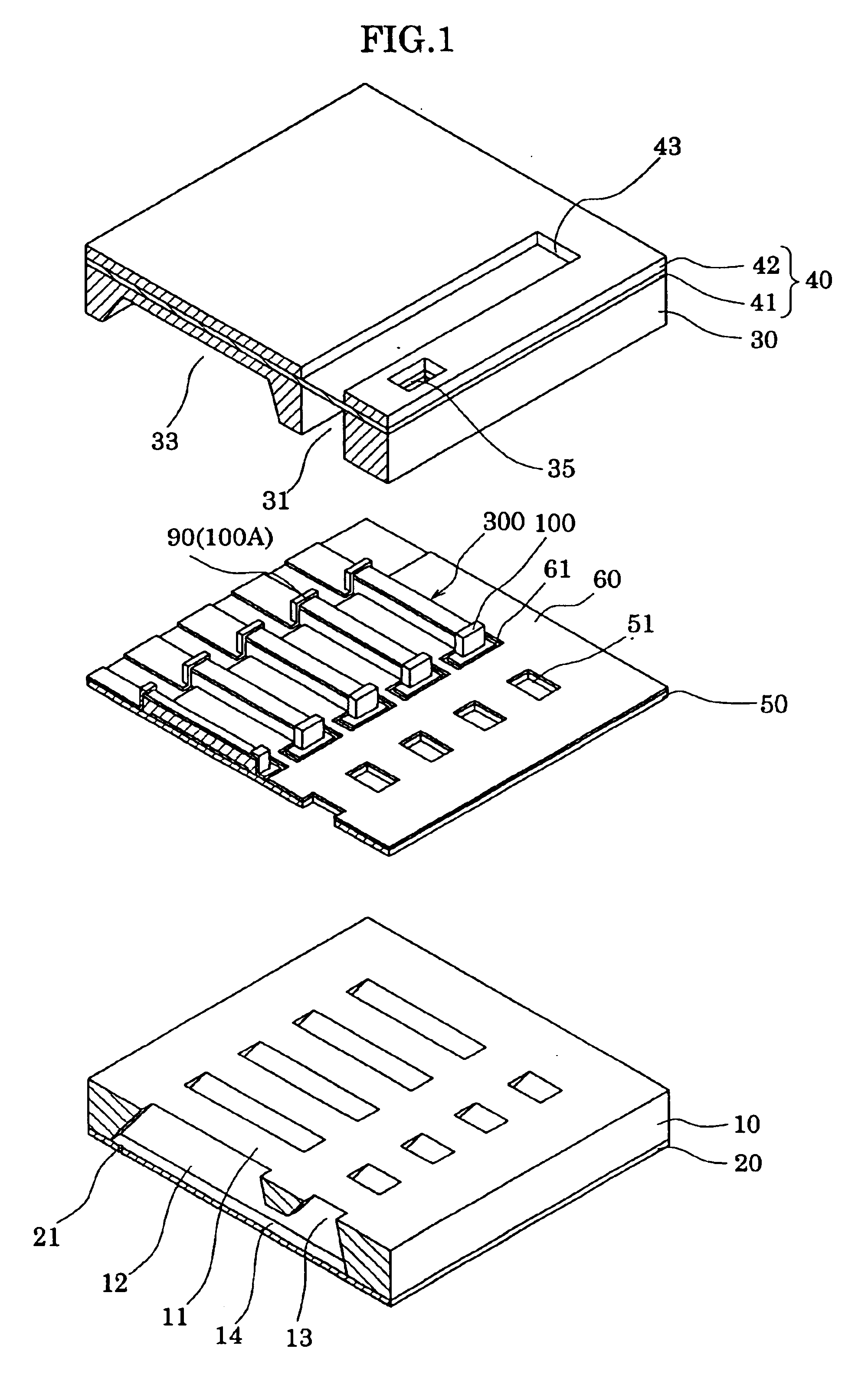
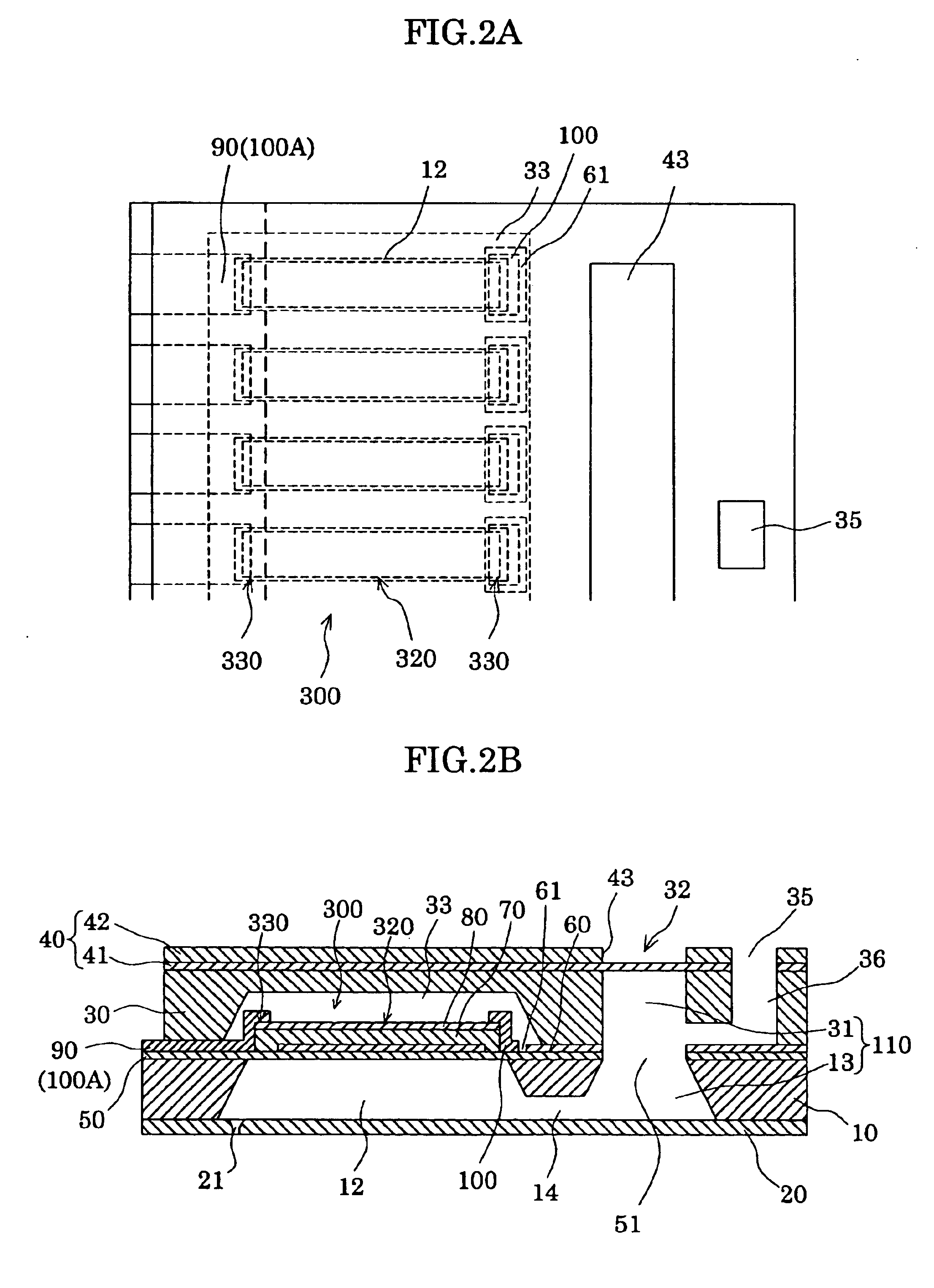
FIG. 1 is an exploded perspective view showing an ink-jet recording head according to a first embodiment of the present invention. FIG. 2A is a plan view of FIG. 1, and FIG. 2B is a section view of FIG. 1.

As illustrated in the drawings, a passage-forming substrate 10 is formed of a silicon single crystal substrate having a plane (110) of the plane orientation in this embodiment. One surface of the passage-forming substrate 10 is an opening surface, and an elastic film 50 having a thickness of 1 to 2 μm, which is made of silicon dioxide and formed by a thermal oxidation, is previously formed on the other surface thereof.

In the passage-forming substrate 10, pressure generating chambers 12 compartmented by a plurality of compartment walls 11 are provided in its width direction. The pressure generating chambers 12 are formed by anisotropically etching the silicon single crystal substrate. A communicating portion 13 is formed on an outer side in a longitudinal direction of ...

embodiment 2

(Embodiment 2)

FIGS. 5A and 5B are a plan view and a cross-sectional view showing a principal part of an ink-jet recording head according to embodiment 2.

As shown in FIGS. 5A and 5B, this embodiment is similar to the first embodiment except that an end portion 60a of the patterned lower electrode film 60 functions as an end portion of the piezoelectric active portion 320, and that the protection layer 100 and the lead electrode 90 being a protection layer 100A are provided as they extend beyond a boundary between the piezoelectric active portion 320 and the piezoelectric non-active portion 330.

In this way, steep stress variation at the boundary between the piezoelectric active portion 320 and the piezoelectric non-active portion 330 can be prevented, whereby damage to the piezoelectric layer 70 associated with the stress variation can be effectively prevented. And also in such a constitution, similar effects to the embodiment 1 can be obtained as a matter of course.

Note that, in this...

embodiment 3

(Embodiment 3)

FIGS. 7A and 7B are a plan view and a cross-sectional view showing a principal part of an ink-jet recording head according to embodiment 3.

In this embodiment, as shown in FIGS. 7A and 7B, the lower electrode film 60 is patterned within the region facing the pressure generating chambers 12 in the vicinity of both end portions in its longitudinal direction, whereby the lower electrode film 60 is provided continuously to the regions facing a plurality of pressure generating chambers 12 arranged in parallel. And each of the piezoelectric non-active portions 330 at the both end portions in the longitudinal direction of the piezoelectric active portions 320 is provided as it extends over peripheral walls outside each of the both end portions in the longitudinal direction of the pressure generating chamber 12.

In other words, in this embodiment, the end portion of the piezoelectric layer 70 of the piezoelectric non-active portion 330 is located outside the region facing the pr...


PUM


Abstract

Provided is an ink-jet recording head that prevents a vibration plate thereof from damage attributed to drive of a piezoelectric element, and an ink-jet recording apparatus. There are provided within a region facing the pressure generating chamber, a piezoelectric active portion, and a piezoelectric non-active portions, the piezoelectric non-active portions being provided on both end portions of the piezoelectric active portion in a longitudinal direction thereof. An electrode wiring is drawn out of an upper electrode which is provided on one end portion in the longitudinal direction of the pressure generating chamber. There is also provided a protection layer on the other end portion in the longitudinal direction of the pressure generating chamber for protecting the vibration plate. Rigidity of the vibration plate is thereby increased.

Description

BACKGROUND OF THE INVENTIONThe present invention relates to an ink-jet recording head for ejecting ink droplets by displacing a piezoelectric element, in which a vibration plate constitutes a part of a pressure generating chamber communicating with a nozzle orifice that ejects ink droplets, and the piezoelectric element is provided via the vibration plate. Moreover, the present invention relates to an ink-jet recording apparatus.As an ink-jet recording head for ejecting ink droplets from a nozzle orifice, in which a vibration plate constitutes a part of a pressure generating chamber communicating with a nozzle orifice that ejects ink droplets, and the vibration plate is deformed by the piezoelectric element to pressurize ink in the pressure generating chamber, the following two types have been put into practical use. One uses a piezoelectric actuator of a longitudinal vibration mode, which stretches and contracts in an axial direction of the piezoelectric element; the other uses a p...

Claims


Application Information

Patent Timeline
IPC IPC(8): B41J2/14B41J2/16
CPCB41J2/14233B41J2/161B41J2/1623B41J2/1629B41J2/1646B41J2/1635B41J2002/14491B41J2002/14241B41J2002/14419
Inventor SHIMADA, MASATOMIYATA, YOSHINAOKAMEI, HIROYUKITAKAHASHI, TETSUSHI
Owner SEIKO EPSON CORP
Why Eureka
Try Eureka