Prosthetic heart value

a heart valve and prosthesis technology, applied in the field of heart valve replacement, can solve the problems of increased workload on the heart, stenosis and insufficiency, and emergency surgery, and achieve the effects of improving hemodynamic performance, nonthrombogenicity, and durability

Inactive Publication Date: 2005-06-28
MEDTRONIC 3F THERAPEUTICS
View PDF1 Cites 366 Cited by
  • Summary
  • Abstract
  • Description
  • Claims
  • Application Information

AI Technical Summary

Benefits of technology

[0012]Accordingly, there is a need in the art for an improved prosthetic heart valve having advantageous hemodynamic performance, nonthrombogenicity, and durability.

Problems solved by technology

Congenital valve abnormalities may be well-tolerated for many years only to develop a life-threatening problem in an elderly patient, or may be so severe that emergency surgery is required within the first few hours of life.
Stenosis and insufficiency may occur concomitantly in the same valve or in different valves.
Both of these abnormalities increase the workload placed on the heart.
However, the currently available options cannot duplicate the advantages of native (natural) heart valves.
Some of the available mechanical valves tend to be very durable, but are problematic in that they are thrombogenic and exhibit relatively poor hemodynamic properties.
Some of the available artificial tissue valves may have relatively low thrombogenicity, but lack durability.
Additionally, even these artificial tissue valves often do not exhibit hemodynamic properties that approach the advantageous hemodynamic performance of a native valve.
Some artificial tissue valves attempt to copy the form of native heart valves; such valves still fall short in durability and in hemodynamic performance.

Method used


Image

  • Prosthetic heart value
  • Prosthetic heart value
  • Prosthetic heart value

Examples


Embodiment Construction

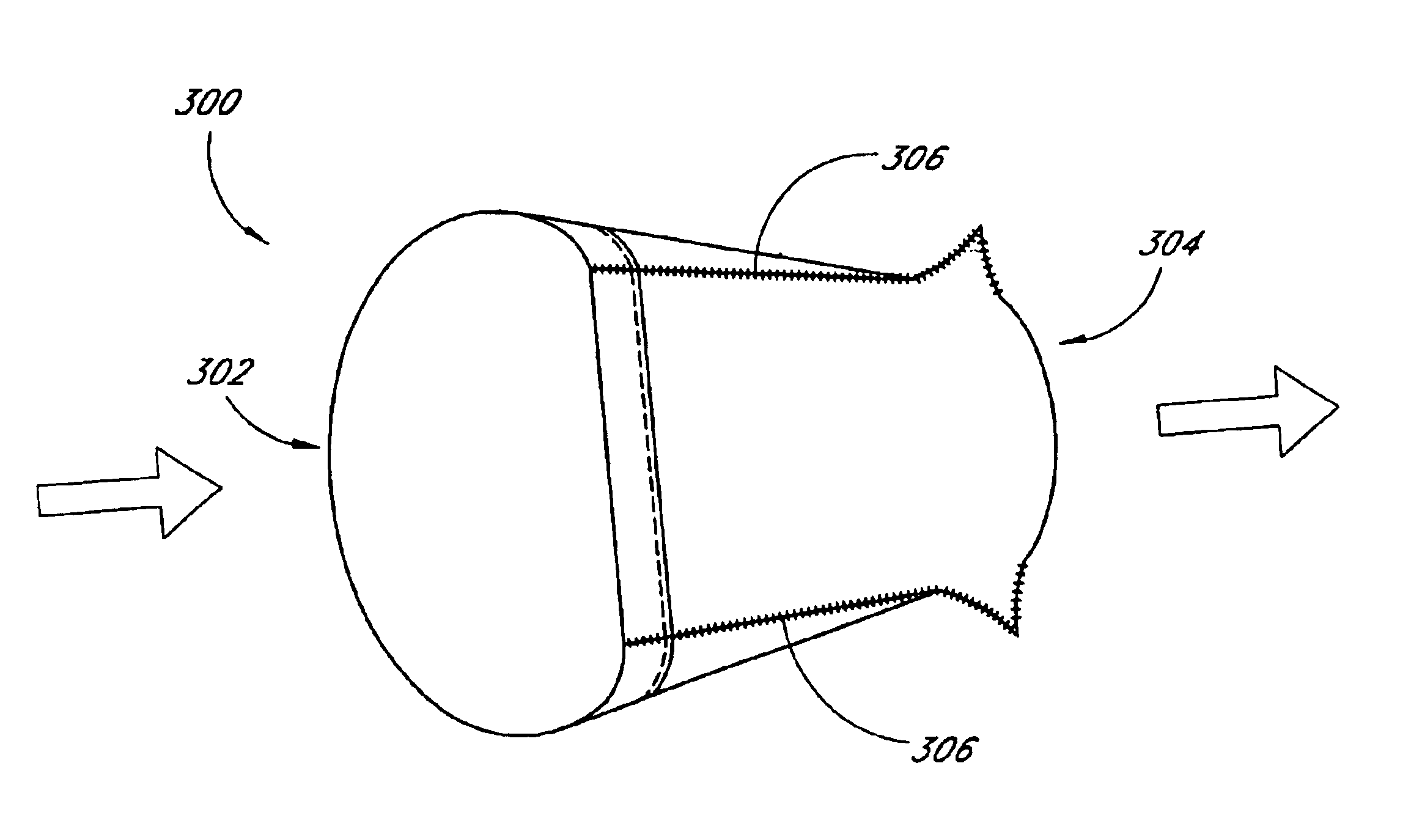
[0067]FIG. 1 shows a cross-sectional cutaway depiction of a normal human heart 50. The left side of heart 50 contains a left atrium 52, a left ventricular chamber 54 positioned between a left ventricular wall 56 and a septum 58, an aortic valve 60, and a mitral valve assembly 62. The components of the mitral valve assembly 62 include a mitral valve annulus 64; an anterior leaflet 66 (sometimes called the aortic leaflet, since it is adjacent to the aortic region); a posterior leaflet 68; two papillary muscles 70 and 72, which are attached at their bases to the interior surface of the left ventricular wall 56; and multiple chordae tendineae 74, which couple the mitral valve leaflets 66 and 68 to the papillary muscles 70 and 72. There is no one-to-one chordal connection between the leaflets and the papillary muscles; instead, numerous chordae are present, and chordae from each papillary muscle 70 and 72 attached to both of the valve leaflets 66 and 68.

[0068]The aorta 80 extends general...


PUM


Abstract

A tubular prosthetic semilunar or atrioventricular heart valve is formed by cutting flat, flexible leaflets according to a pattern. The valve is constructed by aligning the side edges of adjacent leaflets so that the leaflet inner faces engage each other, and then suturing the leaflets together with successive stitches along a fold line adjacent the side edges. The stitches are placed successively from a proximal in-flow end of each leaflet toward a distal out-flow end. During operation, when the leaflets open and close, the leaflets fold along the fold line. Distal tabs extend beyond the distal end of each leaflet. The successive stitches terminate proximal of the distal tab portion so that no locked stitches are placed along the distal portion of the fold line. The tab portions of adjacent leaflets are folded over each other and sewn together to form commissural attachment tabs. The commissural tabs provide commissural attachment points to accommodate sutures and the like in order to secure the tab to a vessel wall, if a semilunar valve, and papillary muscles and / or chordae tendineae if an atrioventricular valve.

Description

RELATED APPLICATIONS[0001]The present application is a divisional of U.S. patent application Ser. No. 09 / 772,526 filed Jan. 29, 2001, now U.S. Pat. No. 6,682,559, the entirety of which is hereby incorporated by reference, which was based on and claims priority to U.S. Provisional Application No. 60 / 178,333, filed Jan. 27, 2000, the entirety of which is hereby incorporated by reference.BACKGROUND OF THE INVENTION[0002]1. Field of the Invention[0003]This invention relates to heart valves, and more particularly relates to replacement of diseased or injured heart valves.[0004]2. Description of the Related Art[0005]There are four valves in the heart that serve to direct blood flow through the two sides of the heart. On the left (systemic) side of the heart are: (1) the mitral valve, located between the left atrium and the left ventricle, and (2) the aortic valve, located between the left ventricle and the aorta. These two valves direct oxygenated blood from the lungs through the left sid...

Claims


Application Information

Patent Timeline
Patent Type & Authority Patents(United States)
IPC IPC(8): A61F2/24
CPCA61F2/2412A61F2/2415A61F2220/0075A61L2300/64
Inventor MYERS, KEITHNGUYEN, CHRISTINE
Owner MEDTRONIC 3F THERAPEUTICS
Why Eureka
Try Eureka