PHOTO-CURABLE COMPOSITION HAVING INHERENTLY EXCELLENT RELEASING PROPERtY AND PATTERN TRANSFER PROPERTY, METHOD FOR TRANSFERRING PATTERN USING THE COMPOSITION AND LIGHT RECORDING MEDIUM HAVING POLYMER PATTERN LAYER PRODUCED USING THE COMPOSITION

Inactive Publication Date: 2008-07-24
SAMSUNG ELECTRONICS CO LTD
View PDF5 Cites 23 Cited by
  • Summary
  • Abstract
  • Description
  • Claims
  • Application Information

AI Technical Summary

Benefits of technology

[0019]Aspects of the present invention provide a photo-curable composi

Problems solved by technology

However, existing photolithography techniques are not suitable for forming ultramicropatterns having a line width of below 100 nm on a substrate.
In addition, existing photolithography involves various steps, including a photoresist coating step, an exposing step, a developing step, an etching step, a cleaning step, etc., that require a complicated patterning process, an extended processing time and a variety of expensive devices and equipment.
Accordingly, existing photolithography methods are disadvantageous from the standpoints of cost and productivity.
However, the nano-imprint lithography technique has a problem in that it is not easy to release a mold from a substrate after pressing the mold onto the substrate without deformation of the polymer pattern layer formed on the substrate.
That is to say, when the mold is separated from the substrate, the polymer pattern layer may adhere to the mold and thus may be partially lifted off with the mold, which may often result in damage to micropatterns transferred onto the substrate.
As described above, a poor releasing property between the mold and the polymer pattern layer on the substrate may damage the transferred polymer pattern layer due to the adhesion and may prevent the mold from being repeatedly used due to contamination.
Therefore, enhancing the releasing property of the mold is

Method used


Image

  • PHOTO-CURABLE COMPOSITION HAVING INHERENTLY EXCELLENT RELEASING PROPERtY AND PATTERN TRANSFER PROPERTY, METHOD FOR TRANSFERRING PATTERN USING THE COMPOSITION AND LIGHT RECORDING MEDIUM HAVING POLYMER PATTERN LAYER PRODUCED USING THE COMPOSITION
  • PHOTO-CURABLE COMPOSITION HAVING INHERENTLY EXCELLENT RELEASING PROPERtY AND PATTERN TRANSFER PROPERTY, METHOD FOR TRANSFERRING PATTERN USING THE COMPOSITION AND LIGHT RECORDING MEDIUM HAVING POLYMER PATTERN LAYER PRODUCED USING THE COMPOSITION
  • PHOTO-CURABLE COMPOSITION HAVING INHERENTLY EXCELLENT RELEASING PROPERtY AND PATTERN TRANSFER PROPERTY, METHOD FOR TRANSFERRING PATTERN USING THE COMPOSITION AND LIGHT RECORDING MEDIUM HAVING POLYMER PATTERN LAYER PRODUCED USING THE COMPOSITION

Examples


example 1

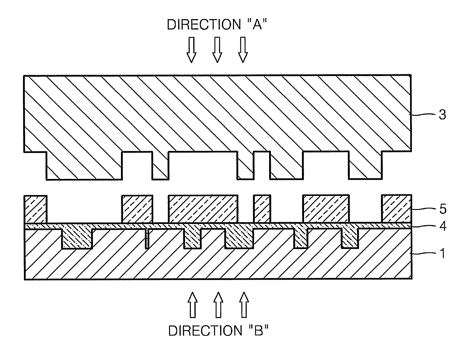
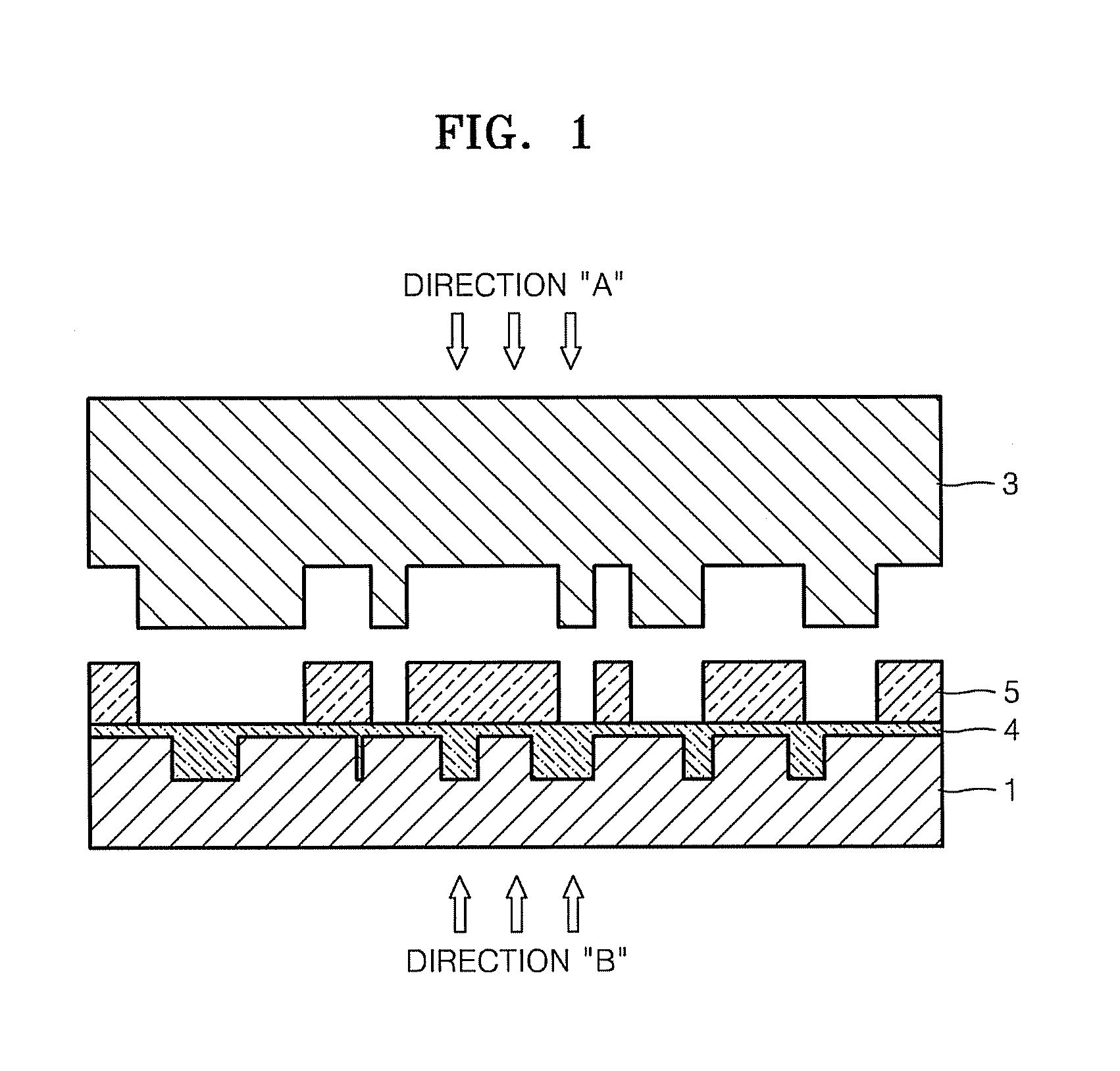
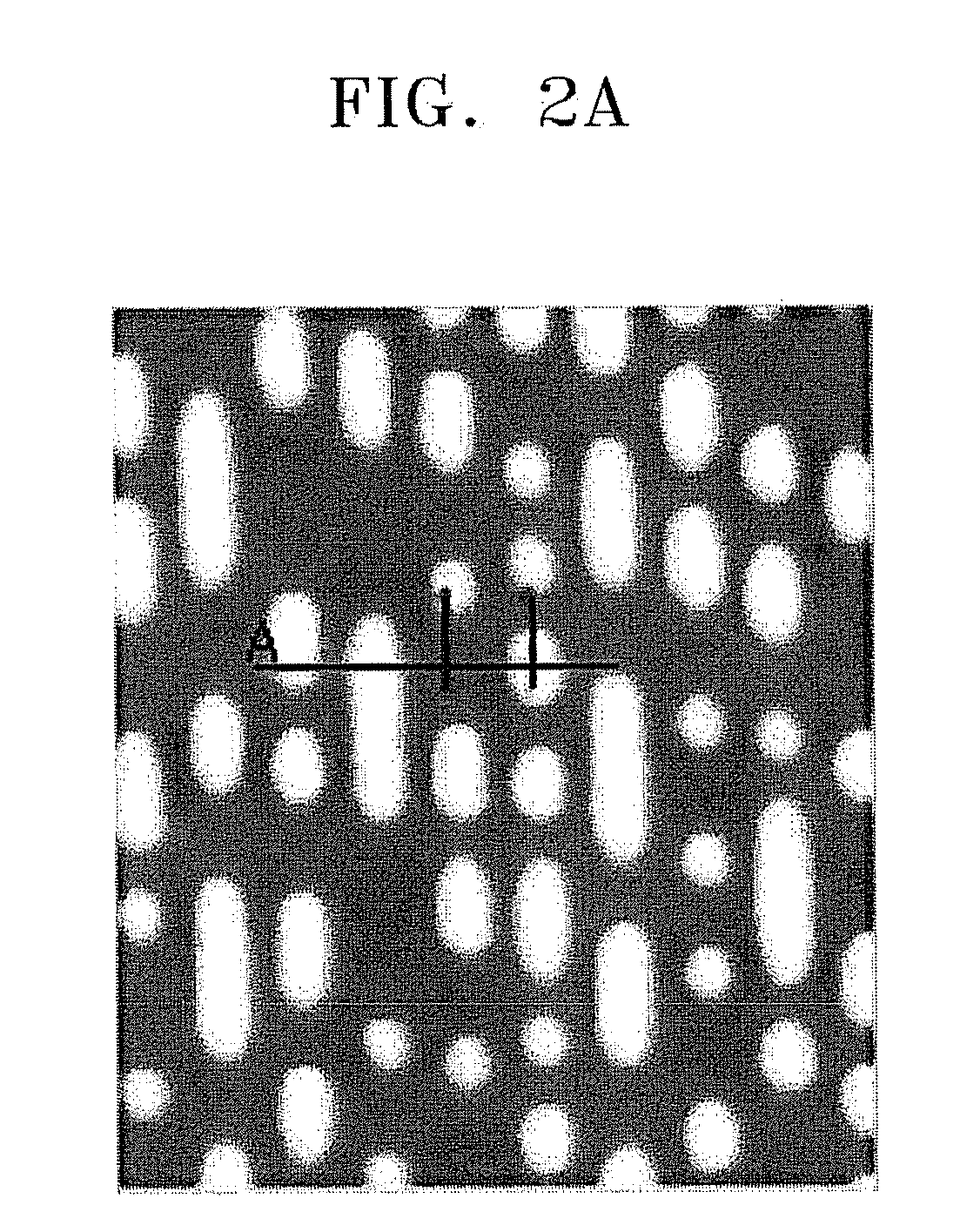
[0087]An optical disc was manufactured by transferring multi-layered patterns onto a substrate using a plastic stamper as a mold, prefabricated by a general method and using the photo-curable resin composition A. FIG. 2A is an atomic force microscope (AFM) view of the plastic stamper used in the current embodiment. In FIG. 2A, bright portions indicate a plurality of convex parts for forming pit patterns on the substrate. FIG. 2B shows a pit depth profile of protrusion and non-protrusion patterns measured by scanning along the line “A” shown in FIG. 2A. In the stamper, an average pit depth scanned along the line “A” was 73.2 nm. The AFM view and pit depth profile were obtained using an Autoprobe M5 manufactured by Park Scientific Instrument.

[0088]An Ag—Pd—Cu (APC) alloy layer having an average thickness of about 30 nm was formed by a vacuum deposition process on an L0 recording layer having a predetermined pattern formed on a surface of a circular polycarbonate transparent substrate ...

example 2

[0098]An optical disc was manufactured by transferring multi-layered patterns onto a substrate using a plastic stamper as a mold prefabricated by a general method and using the photo-curable resin composition B in the same manner as described in Example 1. FIG. 5A is an atomic force microscope (AFM) view of a plastic stamper used in the current example. In FIG. 5A, bright portions indicate a plurality of convex parts for forming pit patterns on the substrate. FIG. 5B shows a pit depth profile of protrusion and non-protrusion patterns measured by scanning along the line “A” shown in FIG. 5A. In the stamper, an average pit depth scanned along the line “A” was 73 nm. The AFM view and pit depth profile were obtained using an Autoprobe M5 manufactured by Park Scientific Instrument.

[0099]FIG. 6A is an AFM view of the polymer pattern layer formed on the substrate after performing the 50th imprinting on the photo-curable composition B using the same stamper. In FIG. 6A, dark portions indica...

example 3

[0101]An optical disc was manufactured by transferring multi-layered patterns onto a substrate using the plastic stamper used in Example 1 and using the photo-curable resin composition C in the same manner as described in Example 1.

[0102]Even after performing the 50th imprinting, no contamination was observed from the stamper. Further, appreciable deformation of the polymer pattern layer was not observed while performing the imprinting 50 times.

[0103]With regard to jitter values, measurements after performing the first and the 50th imprintings were both 7.9%, as measured by the same tester used in Example 1. As to the tilt characteristic in case of recording using a five-layered optical disc, substantially the same evaluation result as in Example 1 was obtained.


PUM

PropertyMeasurementUnit
Percent by massaaaaaaaaaa

Abstract

A photo-curable composition includes 100 parts by weight of a urethane-polydimethylsiloxane copolymerization prepolymer formed by a reaction of a polyol having two or more hydroxyl groups in a molecule thereof, a reactive polydimethylsiloxane having at least one reactive group selected from the group consisting of an amino group, an epoxy group, a carboxy group, a hydroxy group, a halogen atom, a thiol group, and (meth)acrylate, in the side chain or terminal group thereof, and an aliphatic or aromatic polyisocyanate compound; 10-80 parts by weight of (meth)acrylate-based monomer having a functionality of 4 or less, based on 100 parts by weight of the urethane-polydimethylsiloxane copolymerization prepolymer; and 0.1-10 parts by weight of a photoinitiator, based on 100 parts by weight of the urethane-polydimethylsiloxane copolymerization prepolymer. The photo-curable composition has an inherently excellent releasing property and a pattern transfer property. Accordingly, the use of the photo-curable composition can enhance performance efficiency of repeatedly transferring nano- or micro-scale patterns, such as in the fabrication of an optical recording medium.

Description

CROSS-REFERENCE TO RELATED APPLICATIONS[0001]This application claims all benefits accruing under 35 U.S.C. §119 from Korean Patent Application No. 2007-7654, filed on Jan. 24, 2007, Korean Patent Application No. 2007-14977, filed on Feb. 13, 2007, and Korean Patent Application No. 2007-85569, filed on Aug. 24, 2007, in the Korean Intellectual Property Office, the disclosures of which are incorporated herein by reference.BACKGROUND OF THE INVENTION[0002]1. Field of the Invention[0003]Aspects of the present invention relate to a photo-curable composition, a method for transferring a pattern using the same, and an optical recording medium having a polymer pattern layer produced using the same. More particularly, aspects of the present invention relate to a photo-curable composition having an inherently excellent releasing property and pattern transfer property, a method for transferring a pattern using the same, and an optical recording medium having a polymer pattern layer produced us...

Claims


Application Information

Patent Timeline
IPC IPC(8): C08F2/48B29C35/04B41M5/00
CPCB82Y10/00Y10T428/24802C08F2/48C08F283/12C08G18/12C08G18/4825C08G18/61C08G18/672C08G18/725C08L51/085C09D175/16G03F7/0002G03F7/027G03F7/0757G11B7/241G11B7/259G11B7/263B82Y40/00C08G18/48C08L2666/02
Inventor RO, MYONG-DOKIM, HYUN-KIHONG, SOON-YOUNG
Owner SAMSUNG ELECTRONICS CO LTD
Why Eureka
Try Eureka