Hydromechanical speedchange device and vehicle having speed change device mounted thereon

a technology of hydraulic speed change and speed change device, which is applied in the direction of fluid gearing, jet propulsion mounting, gearing, etc., can solve the problems of difficult to sufficiently cool the hst device whose heat generation is difficult, and the non-stage transmission device of the belt type requires frequent maintenance, so as to facilitate the cooling of the hst device and the effect of reducing the size of the entire hmt apparatus

Inactive Publication Date: 2005-02-01
DANFOSS PAUER SOLYUSHENS APS
View PDF14 Cites 22 Cited by
  • Summary
  • Abstract
  • Description
  • Claims
  • Application Information

AI Technical Summary

Benefits of technology

In accordance with the present invention, the input and output shafts (25) and (26) of the hydro-mechanical transmission (HMT) apparatus (T) are disposed in parallel with each other, as a result of which the degree of freedom of laying out the section of the HST device (24) of the HMT apparatus (T) is improved and the downsizing of the entire HMT apparatus (T) is made possible. Further, the section of the HST device (24) is disposed nearer to the outside of the HMT apparatus (T) so that the section of the HST device (24) is located nearer to the outside of the vehicle when mounted thereon. This facilitates cooling of the HST device (24) and provides easy maintenance, thereby achieving improvement in the durability and reliability of the HST device (24). Besides, it is possible to circulate the operating fluid of the HST device (24) separately from other oils such as gear oil. This facilitates maintenance of the characteristics of the operating fluid.
The second invention eliminates the need for the provision of a primary speed-reduction mechanism between the drive source (13) and the transmission, thereby achieving the weight saving, downsizing, and cost reduction of the power train.
In accordance with the third invention, it be

Problems solved by technology

Such a non-stage transmission device of the belt type requires frequent maintenance, particularly in severe conditions.
This inevitably results in elongating, in totality, the piston pump and the piston motor in the axial direction (vehicle width direction).
Because of this, particularly in some vehicles such as an ATV and a motor bicycle in which the transmission apparatus is disposed under a driver's seat of the ride-on type, there actually exists a strict limit on the layout of each component part of the transmission apparatus when trying to avoid interference with the driver's legs.
Further, because of the aforesaid arrangement that the pump and the motor are placed opposite to each other, the HST device sect

Method used


Image

  • Hydromechanical speedchange device and vehicle having speed change device mounted thereon
  • Hydromechanical speedchange device and vehicle having speed change device mounted thereon
  • Hydromechanical speedchange device and vehicle having speed change device mounted thereon

Examples


embodiment 1

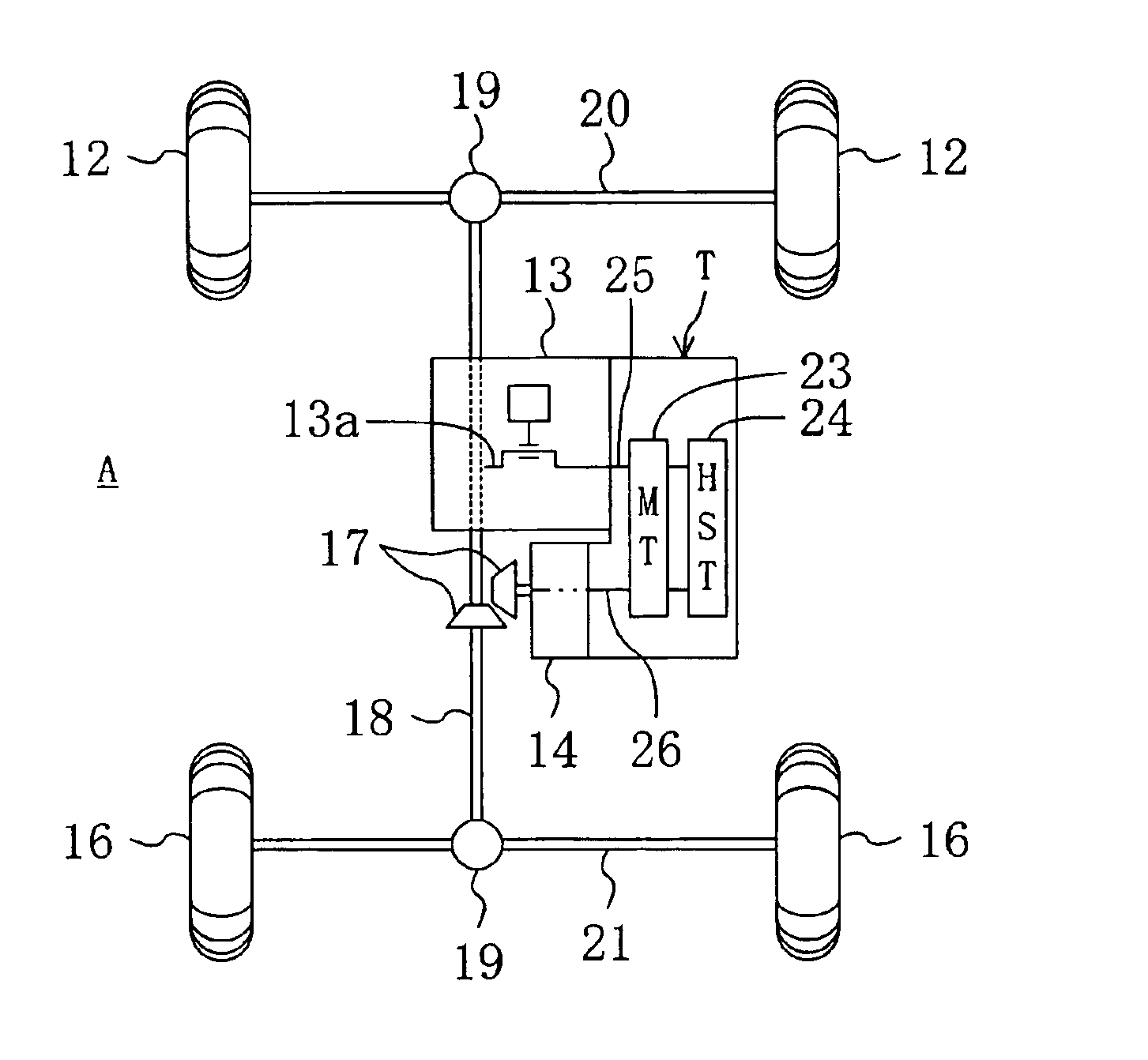
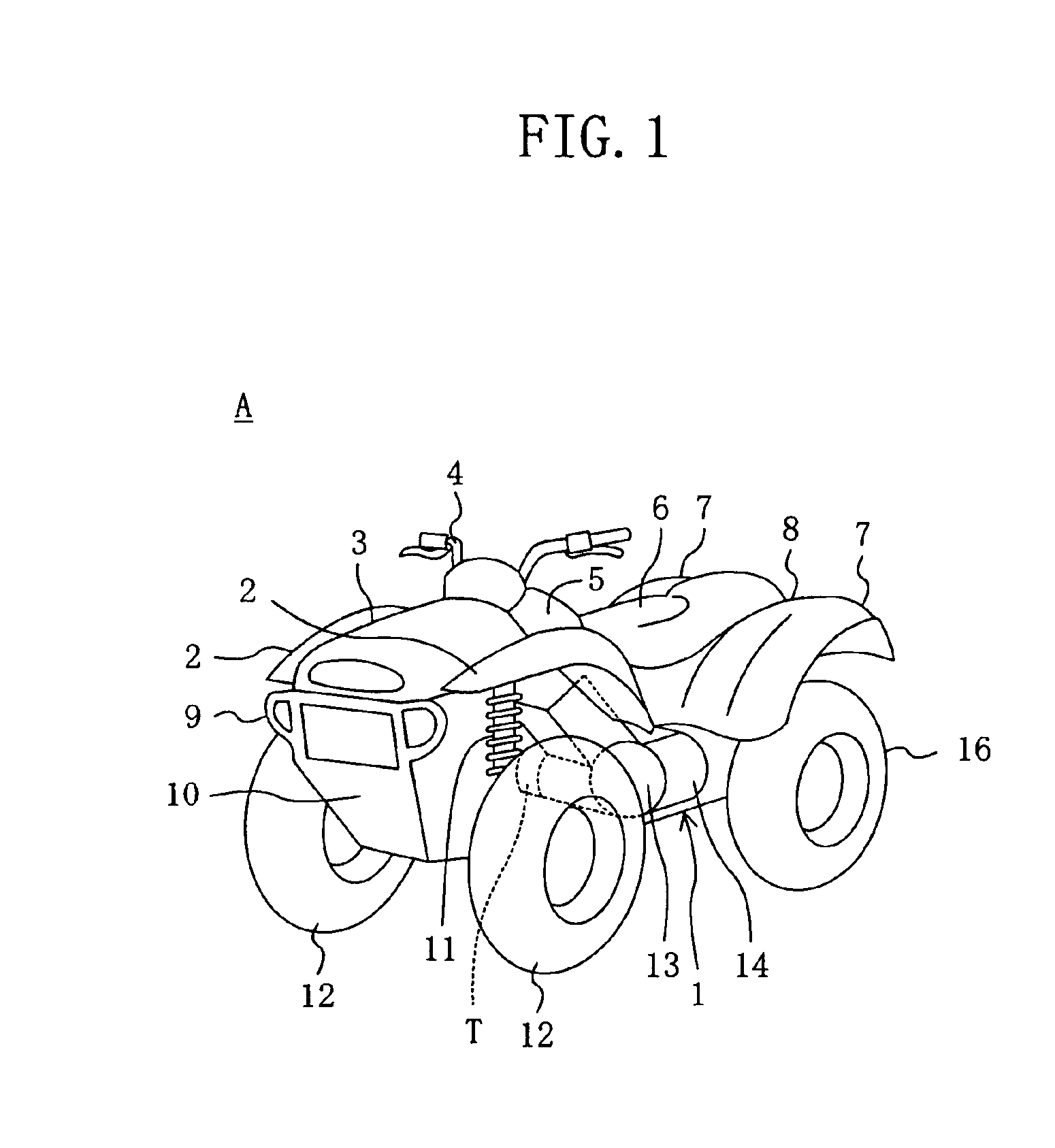
Hereinafter, a first embodiment of the present invention will be described with reference to the Figures. The first embodiment is an embodiment in which a hydro-mechanical transmission (HMT) apparatus (T) according to the present invention is mounted on a four-wheel-drive ATV (A). Referring to FIG. 1, there is shown an external appearance of the ATV (A). Reference numeral (1) denotes a vehicle body comprised of a pipe frame, details of which are left out. Disposed on an upper side of the vehicle body (1) in the order given (from front to rear) are a front cowl (3) having, at either side thereof, fenders (2) and (2), a handle (4), a fuel tank (5), a seat (driver's seat) (6), and a rear cowl (8) having, at either side thereof, fenders (7) and (7).

Provided at the vehicle body forefront under the front cowl (3) is an under cowl (10) formed integrally with a bumper (9). And, a right and left front wheels (12) and (12) are disposed, through strut suspensions (11), at the rear of the under...

embodiment 2

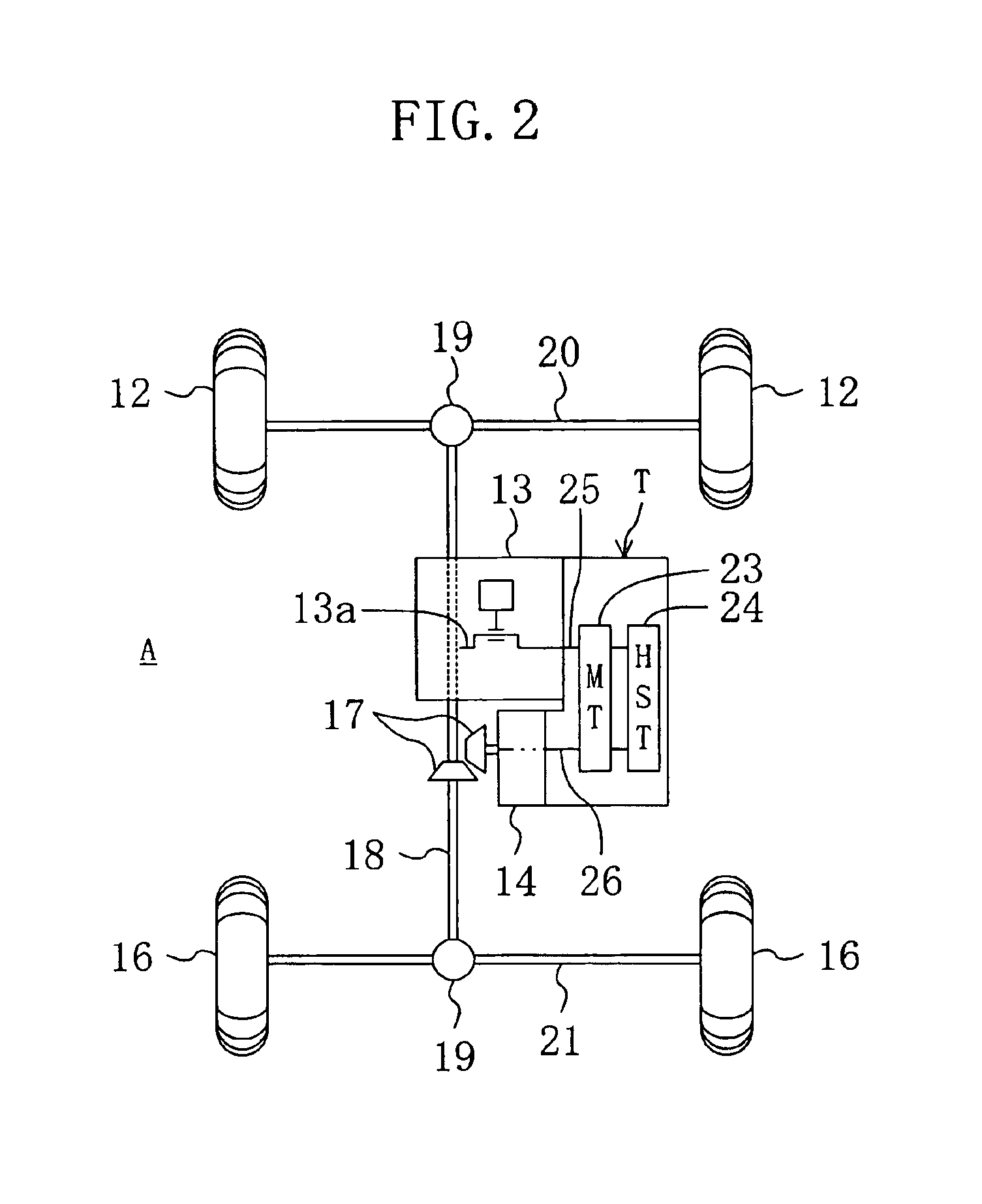
Referring now to FIG. 5, there is shown a power transmission system path construction of an ATV (A) which is equipped with an HMT apparatus (T) according to a second embodiment of the present invention. The second embodiment employs such a structure that the casing of the HMT apparatus (T) can be divided into an HST-side part and an MT-side part. Except for that, the arrangement of the HMT apparatus (T) of the second embodiment is the same as the HMT apparatus (T) of the foregoing first embodiment. Therefore, the same components have been assigned the same reference numerals and their description is omitted. And, as shown in FIG. 5, in accordance with the second embodiment it is arranged such that the casing of the HMT apparatus (T) can be divided into an MT casing (80) for housing therein the MT device (23) and an HST casing (81) for housing therein the HST device (24), and the MT casing (80) is formed integrally with the casing of the secondary transmission device (14).

Referring t...

embodiment 3

Referring now to FIG. 7, there is shown an HMT apparatus (T) according to a third embodiment of the present invention. In the third embodiment, the cylinder barrel (56) is formed as a separate body from the pump shaft portion (25b) and the motor shaft (33) of the input shaft (25) and they are coupled together by clearance fitting, as the piston pump (30) and the motor (31) of the HMT apparatus (T). With this, the input gear (27) of the MT device (23) is formed integrally with the input shaft, and the sun gear (34) of the planetary gear mechanism (28) is formed integrally with the motor shaft (33).

Further, in the piston pump (30) and the motor (31), a valve plate (90) having a general construction is employed in place of the floating type valve plate (65) used in the foregoing embodiments, and it is arranged such that the valve plate (90) is pressed and energized against a sliding contact plate member (91) which is disposed at the rear side of the end cap (41).

Furthermore, in the pis...


PUM


Abstract

An HMT apparatus (T) is mounted on a vehicle (A). In the HMT apparatus (T), input rotational force from an engine (13) is once divided into two systems which are then transmitted by an MT device (23) and by an HST device (24) respectively and are re-synthesized for transfer toward wheels (12) and (16). The HMT apparatus (T) is disposed on the vehicle-body right side of the engine (13) which is sideways-mounted on a vehicle body (1), and its input and output shafts (25) and (26) are disposed in parallel with a crank shaft (13a) of the engine (13) and are disposed to run parallel with each other. The input shaft (25) is coupled directly to the crank shaft (13a) and an input gear (27) of the MT device (23) is mounted on the input shaft (25), and a hydraulic piston pump (30) of the HST device (24) is connected to the right side end of the input shaft (25). A planetary gear mechanism (28) of the MT device (23) is connected to the right side end of the output shaft (26), and a hydraulic piston motor (31) of the HST device (24) is connected to the right side of the planetary gear mechanism (28). By virtue of such arrangement, it is possible to improve the degree of freedom of the layout of each component of the HMT apparatus (T), to reduce axial dimensions, and further to provide improvement in the cooling property and maintenance property of the section of the HST device (24).

Description

TECHNICAL FIELDThe present invention relates in general to a hydro-mechanical transmission apparatus which is a combination of a hydro-static transmission device implemented by a variable displacement piston pump / motor and a mechanical transmission device, and to a vehicle which is equipped with such a transmission apparatus. This invention relates in particular to the technical field of the layout of an input and output shafts of a transmission apparatus suitable for cases where the transmission apparatus is disposed under the driver's seat, as in an all-terrain vehicle (ATV) (e.g., a three-wheeled buggy vehicle and a four-wheeled buggy vehicle), a tractor, a motor bicycle, and other vehicle.BACKGROUND ARTAs a transmission apparatus for use in vehicles such as a four-wheeled buggy vehicle, transmission apparatus of the type having a continuously variable transmission device by a belt power transmission mechanism have been used extensively. Such a non-stage transmission device of th...

Claims


Application Information

Patent Timeline
IPC IPC(8): B60K17/10B60K17/34B60K5/04B60K17/04F16H47/04F16H57/02F16H57/023F16H57/037F16H57/038F16H57/039
CPCB60K17/10B60K5/04B60K17/34F16H2037/088B60Y2200/124F16H47/04B60Y2200/12
Inventor TANI, NOBUYUKI
Owner DANFOSS PAUER SOLYUSHENS APS
Why Eureka
Try Eureka