
Efficiencies for piston engines or machines

a technology of efficiencies and pistons, applied in machines/engines, mechanical equipment, positive displacement liquid engines, etc., can solve problems such as slapping of pistons against cylinder walls, and achieve the effects of reducing shaft counter weights, improving efficiency, and increasing vibration

Active Publication Date: 2007-03-15
FISHER PATRICK T
View PDF26 Cites 20 Cited by
  • Summary
  • Abstract
  • Description
  • Claims
  • Application Information

AI Technical Summary

Benefits of technology

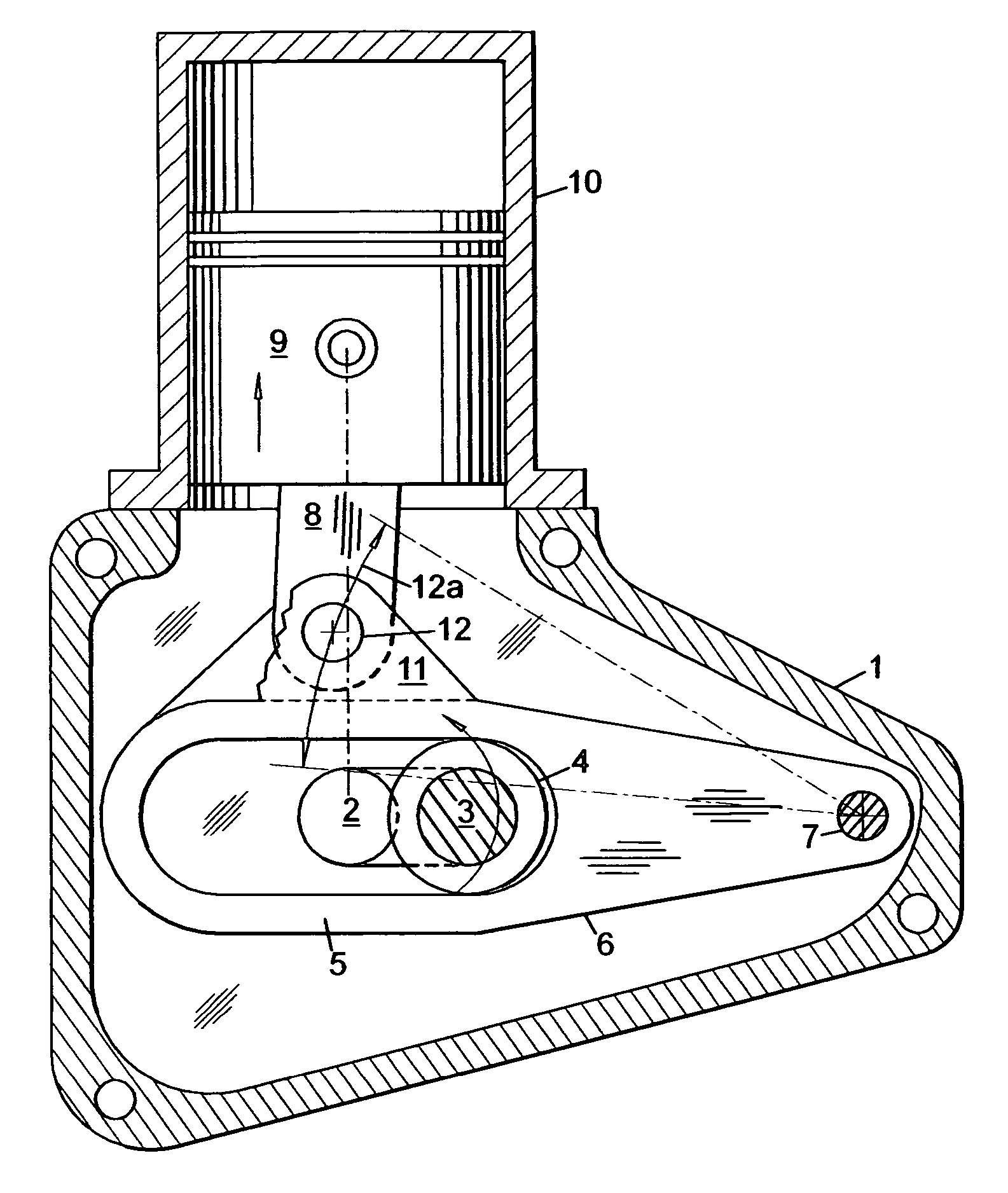
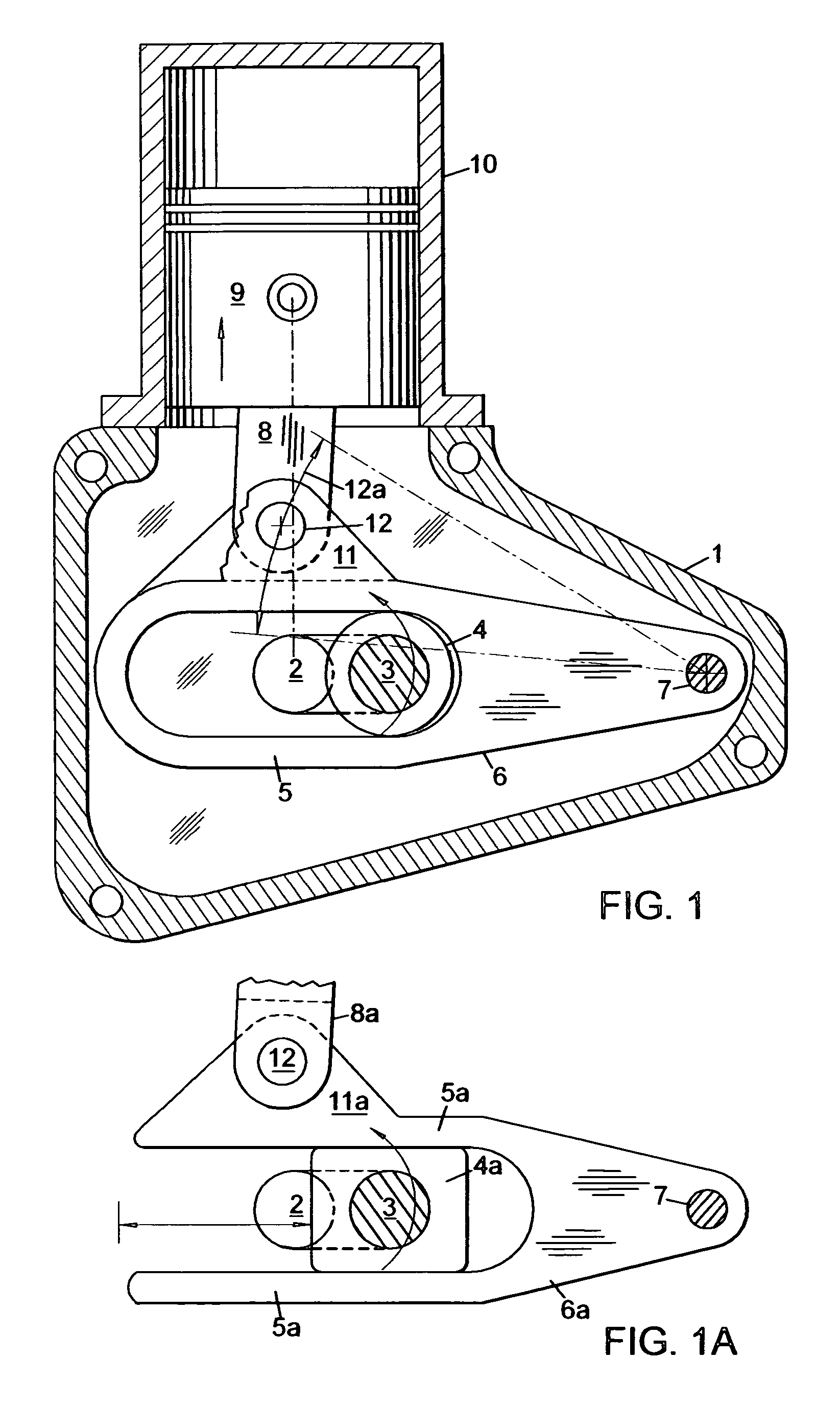
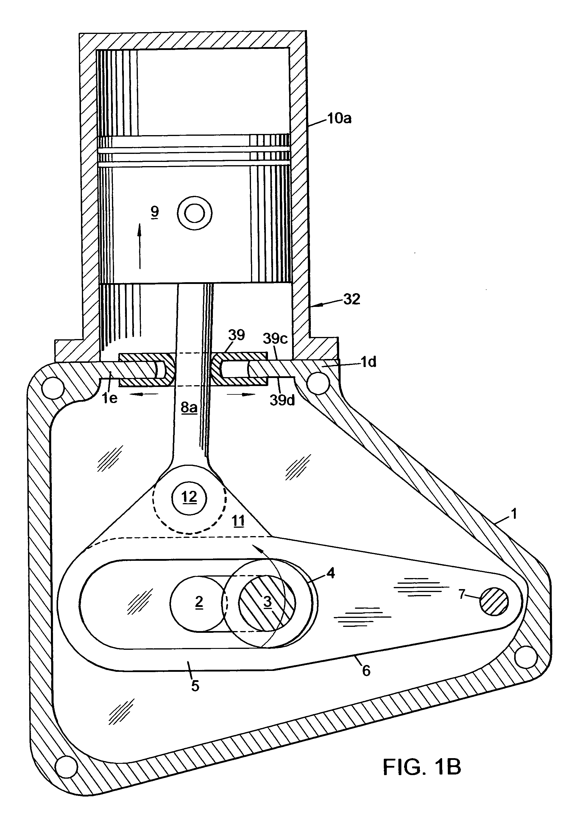
[0016] This piston machine invention provides novel yoke-arm crankshaft, radial plate cam and crankshaft beam mechanisms. These mechanisms can improve the performance of reciprocating engines, compressors and liquid pumps by the novel use of pivoting arms and beams that provide several advantages. One advantage is that the arms and beams maintain the piston rod alignment in a path close to the axial line of the cylinders. This substantially reduces piston friction caused by piston rod angularity. Reduced piston friction has the benefits of longer engine life, less cooling, higher efficiencies and increased power. The mechanical efficiency of the invention is generally over 90% and greater than 94% can be achieved when using anti-friction bearings.
[0017] Another advantage of these improved mechanisms is increased piston dwell that allows combustion to take place for a longer duration near the top of the stroke. The invention's cam, cam beam and crankshaft beam mechanisms provide 15-40% longer piston dwell compared to prior art machines. For the invention's opposed-piston, two yoke-arm crankshaft arrangement, piston dwells of 250% more than prior art yoke crankshaft or conventional crankshaft engines can be achieved. The invention's yoke-arm crankshaft dwell increases are provided by the yoke design, the yoke-arm's pivoting angle and / or relative alignment of the cylinders; and for the crankshaft beam mechanism, favorable rod angularity and cylinder positioning determine piston dwell. For the cam, piston dwell can be adjusted by modifying the cam's contour design and by cylinder positioning. This feature of longer piston dwell provides substantially improved fuel efficiencies, increased power and reduced emissions.
[0018] Because piston rods are not directly connected to a crankshaft, piston rod angularity and secondary inertia vibratory forces are virtually eliminated. The result is that the invention's yoke-arm crankshaft, cam and crankshaft beam mechanisms have substantially lower vibration in comparison to today's conventional machines.

Problems solved by technology

Piston knocking is a problem for conventional diesel engines which have high combustion forces and oscillating piston rods that cause piston slap against the cylinder walls.

Method used


Image

  • Efficiencies for piston engines or machines
  • Efficiencies for piston engines or machines
  • Efficiencies for piston engines or machines

Examples


Embodiment Construction

[0062] The invention provides reciprocating piston machines with novel yoke-arm crankshaft, plate cam and eccentric beam mechanisms which include the new and improved use of pivoting arms. Reduced piston friction and increased piston dwell are some of the fundamental advantages featured by the invention. Some arrangements described are: (1) single-cylinder, (2) in-line twin, (3) opposed two-cylinder, (4) V-twin, and (5) semiradial and radial.

[0063] These reciprocating piston machines relate to internal combustion engines, compressors, steam engines, fluid motors and pumps; the machines operate with piston power drive equipment that includes vehicles, aircraft, boats, air conditioners and power tools.

[0064]FIGS. 1-5 are arranged and function somewhat similar to conventional crankshaft engines except for the addition of yoke-arm(s) 6 and crankpin roller bearing(s) 4 that provide significant advantages.

[0065] In FIG. 1, there is shown one embodiment of the invention that is a single...


PUM


Abstract

Disclosed are crankshaft, single-plate cam and beam mechanisms that provide significant improvements in performance for 2 & 4-stroke engines, compressors and pumps. These cost effective mechanisms include linkages with the new and improved use of pivoting arms that operate with a variety of cylinder arrangements. One embodiment of the crankshaft mechanism has its crankpin roller positioned within a novel yoke-arm. The cam mechanism uses a pair of centrally positioned parallel links that are connected to roller cam followers and single or diametrically-opposed pistons. A pair of laterally extending follower arms connects to the ends of the links to provide support and alignment for the piston rods. Between the reciprocating links, cam followers and follower arms is a rotating odd-lobe plate cam. A beam mechanism uses opposite-direction extending balancing beams that are connected to links, cam followers and piston rods.

Description

CROSS-REFERENCE TO RELATED APPLICATIONS [0001] Not applicable STATEMENT REGARDING FEDERALLY SPONSORED RESEARCH OR DEVELOPMENT [0002] Not applicable REFERENCE TO MICROFICHE APPENDIX [0003] Not applicable TECHNICAL FIELD OF THE INVENTION [0004] The present invention relates to reciprocating piston power drive equipment that operates with reciprocating engines, compressors, fluid motors and pumps. Piston equipment includes vehicles, aircraft, boats, air conditioners and power tools. BACKGROUND OF THE INVENTION [0005] Conventional piston engines and compressors use a crankshaft with an attached piston rod linkage, thereby causing limitations in the areas of efficiency, balance, noise, power shaft rpm reduction, weight and cost. These limitations are caused by six primary disadvantages: (1) Conventional crankshaft mechanisms oscillate the piston rods causing rod vibrations and piston side thrust resulting in piston friction. (2) Conventional crankshaft mechanisms have constraints for inc...

Claims


Application Information

Patent Timeline
Patent Type & Authority Applications(United States)
IPC IPC(8): F02B75/32F16C7/00F02B75/22
CPCF01B9/023F02B75/32F04B27/02F04B39/0094F04B27/0414F04B27/053F04B27/0404
Inventor FISHER, PATRICK T.
Owner FISHER PATRICK T
Learn More