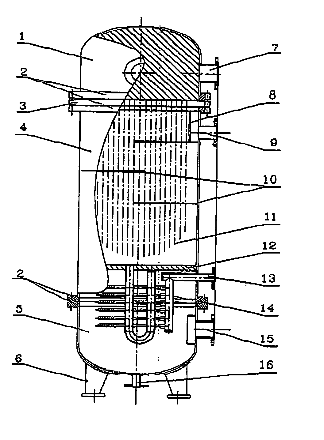
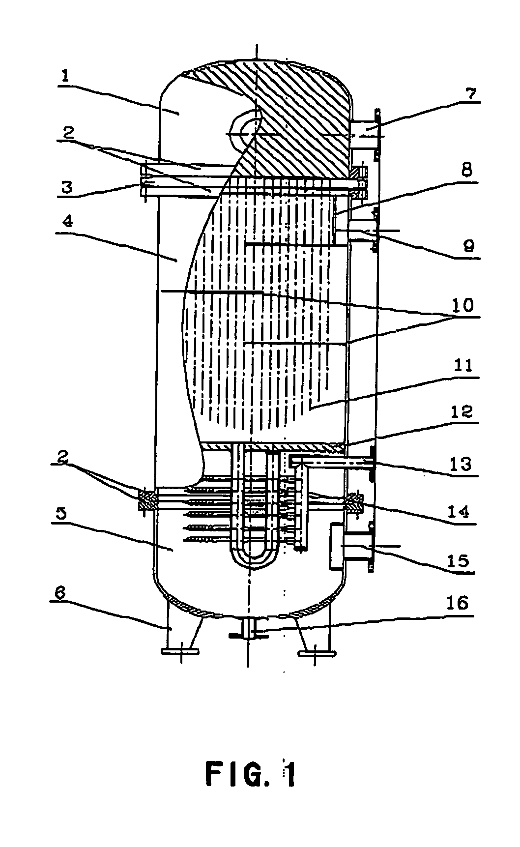
Complex flow-path heat exchanger having U-shaped tube and cantilever combined coil

a heat exchanger and complex technology, applied in heat exchange apparatus, lighting and heating apparatus, stationary conduit assemblies, etc., can solve the problems of low heat exchange efficiency and considerable low heat exchange coefficient, and achieve high heat exchange coefficient, small steam flow resistance, and high heat exchange coefficient

Inactive Publication Date: 2005-05-26
SHANDONG UNIV
View PDF12 Cites 20 Cited by
  • Summary
  • Abstract
  • Description
  • Claims
  • Application Information

AI Technical Summary

Benefits of technology

[0005] The technical gist according to the present invention is as follows: after entering into the heat exchanger, steam is firstly cooled and condensed in the shell side of the U-shaped tube, thereafter entering into tube side of the cantilever combine coils, which are disposed within the same one shell, for a secondary heat exchange, and subsequently flowing out of the heat exchanger after being subcooled. Such steam-water heat exchanger having a complex flow path are advantageous in a small steam flow resistance of shell side of the U-shaped tube; a higher condensate water flow velocity in the cantilever combined coils; a high heat exchange coefficient; good coordination of the temperature fields of the hot and cold fluids in the heat exchanger; and a high heat exchange efficiency.
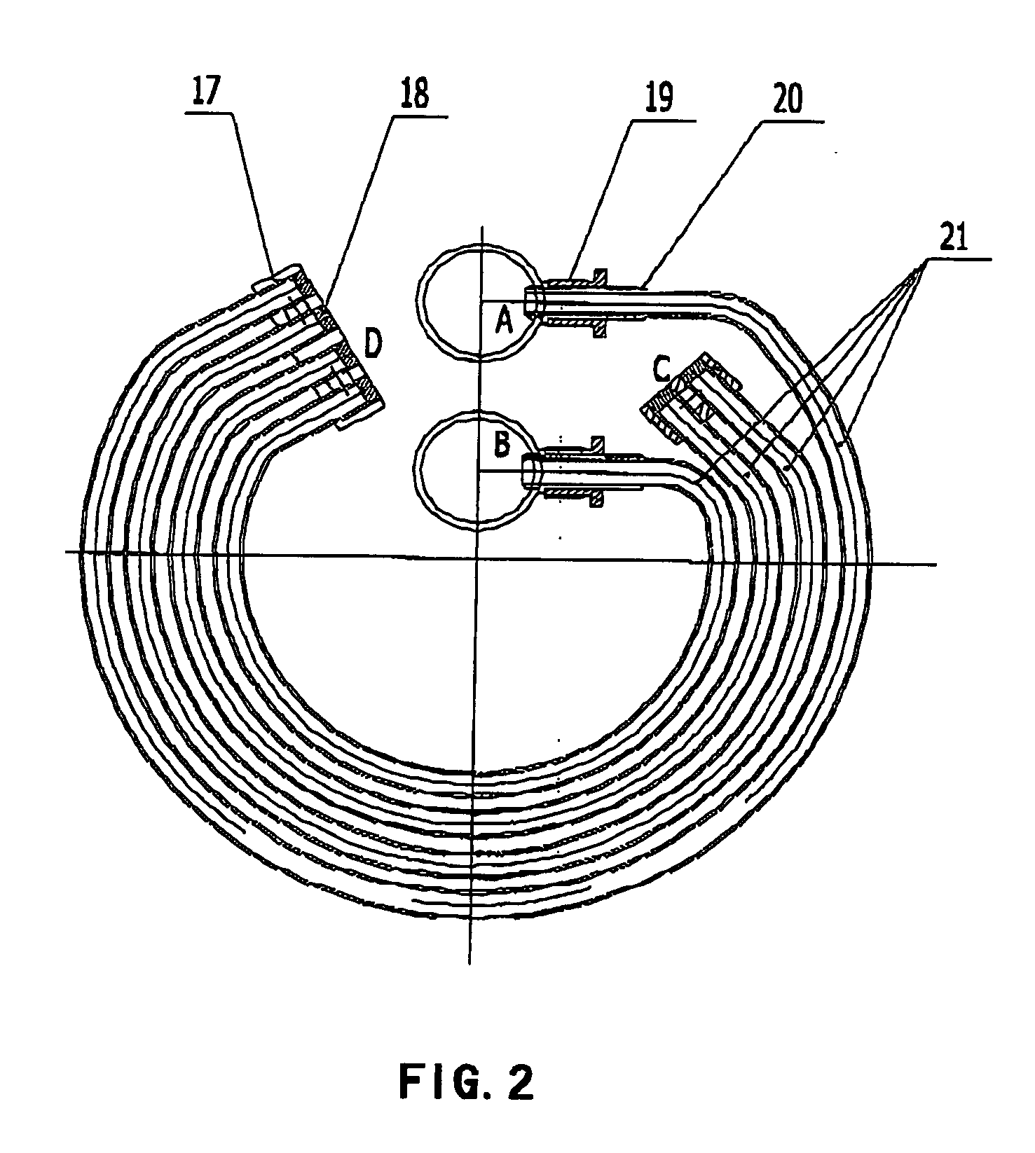
[0006] The cantilever combined coil has a fixed end, an absolutely free end, and a relatively free end. The element exhibits more spring characteristics with respect to vibration, enabling the continuously pulsating water flow to excite vibration more easily; moreover, the complex structure thereof performs an inhibiting effect during the vibration so that any change of any small force can prevent the continuation of the existing frequency vibration, while the main flow disturbance rapidly makes vibration to go on. Thus, the low frequency vibration within a given rang is thereby generated, making disturbance to the water flow, but no damage will be incurred due to strong vibration, and therefore a higher heat transfer coefficient can be achieved at low flow velocity. The characteristics of the structure of the cantilever combined coil in response to fluid induction vibration have the resonance characteristic when the flow pulsating frequency is equal to the structural natural frequency and the sub-resonance characteristics when the flow pulsate at ½ natural frequency. Consequently, the cantilever combined coil can be induced to vibrate by a lower frequency pulsating, and this vibration is in the sub-resonance region, so that no damage will be incurred due to violent vibration.
[0007] The present heat exchanger comprises the vertical type and the horizontal type. The arrangement of the cantilever combined coils according to the present invention in the present heat exchanger differs from that of the conventional tubular type heat exchange elements, thereby completely eliminating the need of the tube-plate coupling structural fashion, and instead directly connecting the cantilever combined coils in a plurality of groups onto the hot media tube in parallel. The structural form of the cantilever combined coils sets the heat exchange elements free out of the conventional tube-plate structure, so that the spatial arrangement of the heat exchanger is made more flexible, and the steam-water and water-water complex heat exchange within the same one shell can be realized; under the inducement of the pulsating flow, the energy distribution over the cantilever combined coils at respective natural frequency has a significant influence on the operating condition of the cantilever combined coil bundles. Upon experiments, the bending radius, and the diameter and the wall thickness of the circular tube of the cantilever combined coils can be screened out to determine the specific dimension of the different models, so that such constructed inducing vibration system as above makes the variation of the water velocity not to have a significant influence on the vibration, consequently, the cantilever combined coils can be adapted to the variation of different loads, while maintaining good vibration characteristics. The thermal efficiency of the present heat exchanger is more than 98%, and the maximum heat exchange capacity is 7 MW, and on the other hand, the heat source is generally saturated steam at the pressure 0.6 Mpa. The present heat exchanger can maintain the production output quite well, even when the steam pressure reduces to 0.1 MPa. The advantages of the present heat exchanger include the small size, the simple construction, a high energy utilization rate, etc., therefore, the present heat exchanger can be a new generation product relative to the currently-used conventional low-temperature, low-pressure and corrosion-free heat exchangers.

Problems solved by technology

In a word, both of said heat exchangers employ a single flow path of the heat exchange medium, therefore, it is difficult to subcool the steam after it is condensed, consequently it is extremely difficult to prevent the steam from occurring to secondarily flash off; moreover, due to the quite low flow velocity in the condensate water tube of the steam-water heat exchanger employing the single flow path, the heat exchange coefficient is considerably low, furthermore, due to the fact that no phase change occurs, temperature-difference-field of hot and cold fluids are non-uniform, and the temperature difference fields of the hot and cold fluids can not coordinate with each other very well, so the heat exchange efficiency is low.

Method used


Image

  • Complex flow-path heat exchanger having U-shaped tube and cantilever combined coil
  • Complex flow-path heat exchanger having U-shaped tube and cantilever combined coil
  • Complex flow-path heat exchanger having U-shaped tube and cantilever combined coil

Examples


Embodiment Construction

[0013] The embodiments of the present invention will be described as follows. FIG. 1 and FIG. 2 show the construction on the whole. In the heat exchanger according to the present invention arrange vertically, the outlet pipe 7 of the heated water and the inlet pipe 15 of the heated water are disposed on the upper shell cover 1 and the lower shell cover 5 respectively, the steam inlet pipe 9 is disposed on the upper half portion of the cylinder body, and the drainage port 16 and the condensate water outlet pipe 13 are disposed on the lower shell cover.

[0014] The shell body of the heat exchanger is comprised of the cylinder body 4, the flange 2, and the oval shell cover and like. The lower half portion of the cylinder body 4 is provided with the partition plate 12 for dividing the cylinder body 4 into an upper portion and a lower portion, wherein the upper half portion of the cylinder body 4 is provided with the U-shaped tube bundles serving as heat transfer elements, and the lower h...


PUM


Abstract

A complex flow-path heat exchanger having U-shaped tube and cantilever combined coil, which can achieve, in this type heat exchanger, a simple construction, a complex flow of steam within the same one heat exchange shell body, a high heat exchange efficiency, and a low energy loss. The technical gift of the present invention is that, after entering into the heat exchanger, steam firstly effects heat exchange on the U-shaped tube flow path shell side to be cooled and condensed, thereafter entering into flow path tube side of the cantilever combined coil, which are disposed within the same one shell, for a secondary heat exchange, and subsequently flowing out of the heat exchanger after being subcooled. Such steam-water heat exchanger having a complex flow path are advantageous in a small steam flow resistance of the U-shaped tube flow path shell side; a higher condensate water flow velocity in the cantilever combined coils flow path tube; a high heat exchange coefficient; good coordination of the temperature difference fields of the hot and cold fluids in the heat exchanger; and a high heat exchange efficiency. Therefore, the present heat exchanger can be a new generation product relative to the currently-used conventional low-temperature, low-pressure and corrosion-free heat exchangers.

Description

FIELD OF THE INVENTION [0001] The present invention relates to a steam-water heat exchanging device suitable to be used in multipurpose hot water supply systems. BACKGROUND OF THE INVENTION [0002] Conventional steam-water heat exchanging devices are largely divided into two types: one is a regenerative heat exchanger, such as a tube bank type heat exchanger and a submersible type heat exchanger, which is in form of usually a large-sized water storage container, in which tube bundles are arrange, steam flowing on the tube side, and water flowing in the shell side, wherein the heat exchanger has a large volume, the heat exchange efficiency thereof is low, and the energy loss thereof is high; the other is an instantaneous heat exchanger, commonly for example, an U-shaped tube type heat exchanger and a plate heat exchanger, etc., in which steam flows on the shell side, and water flows on the tube side, wherein the heat loss of this type heat exchanger is relatively high, because the tem...

Claims


Application Information

Patent Timeline
Patent Type & Authority Applications(United States)
IPC IPC(8): F22D1/32F28D7/00F28D7/06F28F13/10
CPCF22D1/32F28D7/0066F28F13/10F28D7/06F28D7/0083
Inventor CHENG, LINGUO, ZENGYUAN
Owner SHANDONG UNIV
Why Eureka
Try Eureka