
Mixer for synthetic quartz

a synthetic quartz and mixer technology, applied in clay mixing apparatus, transportation and packaging, supply apparatus of sold ingredients, etc., can solve the problems of unfavorable mixing, large amount of dust raised in the mixer, and low mixing efficiency, and achieves small flow resistance and easy cleaning

Inactive Publication Date: 2020-08-20
VEEGOO TECH CO LTD
View PDF5 Cites 21 Cited by
  • Summary
  • Abstract
  • Description
  • Claims
  • Application Information

AI Technical Summary

Benefits of technology

This patent introduces an artificial quartz stone mixer that has several technical advantages over existing mixers: easy cleaning, low flow resistance, smooth resin dropping process, and friendly installation position. The mixer is designed with an open and vacant space at the top, which makes it easier to clean and has low flow resistance. There is no obstruction in the resin flow path, so the process of falling the resin is smooth. The overall structure of the mixer is simple and functionally similar to existing mixers, but it can reduce production and maintenance costs for customers.

Problems solved by technology

Therefore, the resin is often accumulated at a certain position at the bottom of the mixing tank, which is likely to cause uneven mixing effect and very low mixing efficiency.
However, during the mixing process, a large amount of dust will be raised in the mixer, and the resin flows out from the outlet of the outlet pipe.
In addition, the installed outlet pipe needs to consider the installation position and installation direction in order to prevent interference with the mixing shaft, making the overall structure of the mixer more complicated, which is not conducive to installation and saving production costs.
Moreover, after stirring, due to the structural limitation of the annular groove, it is difficult to completely discharge the resin in the annular groove into the outlet pipe, which easily leads to resin accumulation.
Over time, the resin agglomerates which makes the flow of resin not smooth and affects production.

Method used


Image

  • Mixer for synthetic quartz
  • Mixer for synthetic quartz
  • Mixer for synthetic quartz

Examples


Embodiment Construction

[0075]The technical solutions of the present invention will be further described below with reference to the drawings and through specific implementations.

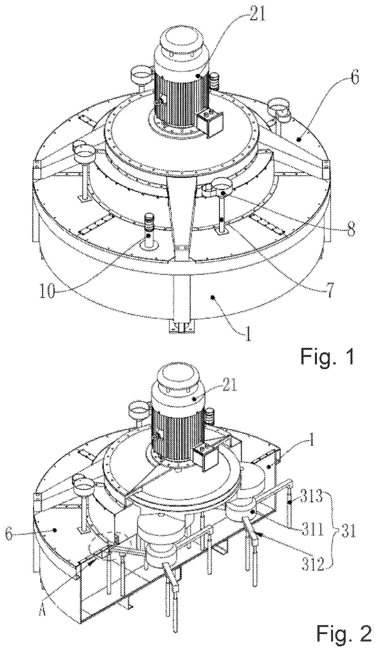
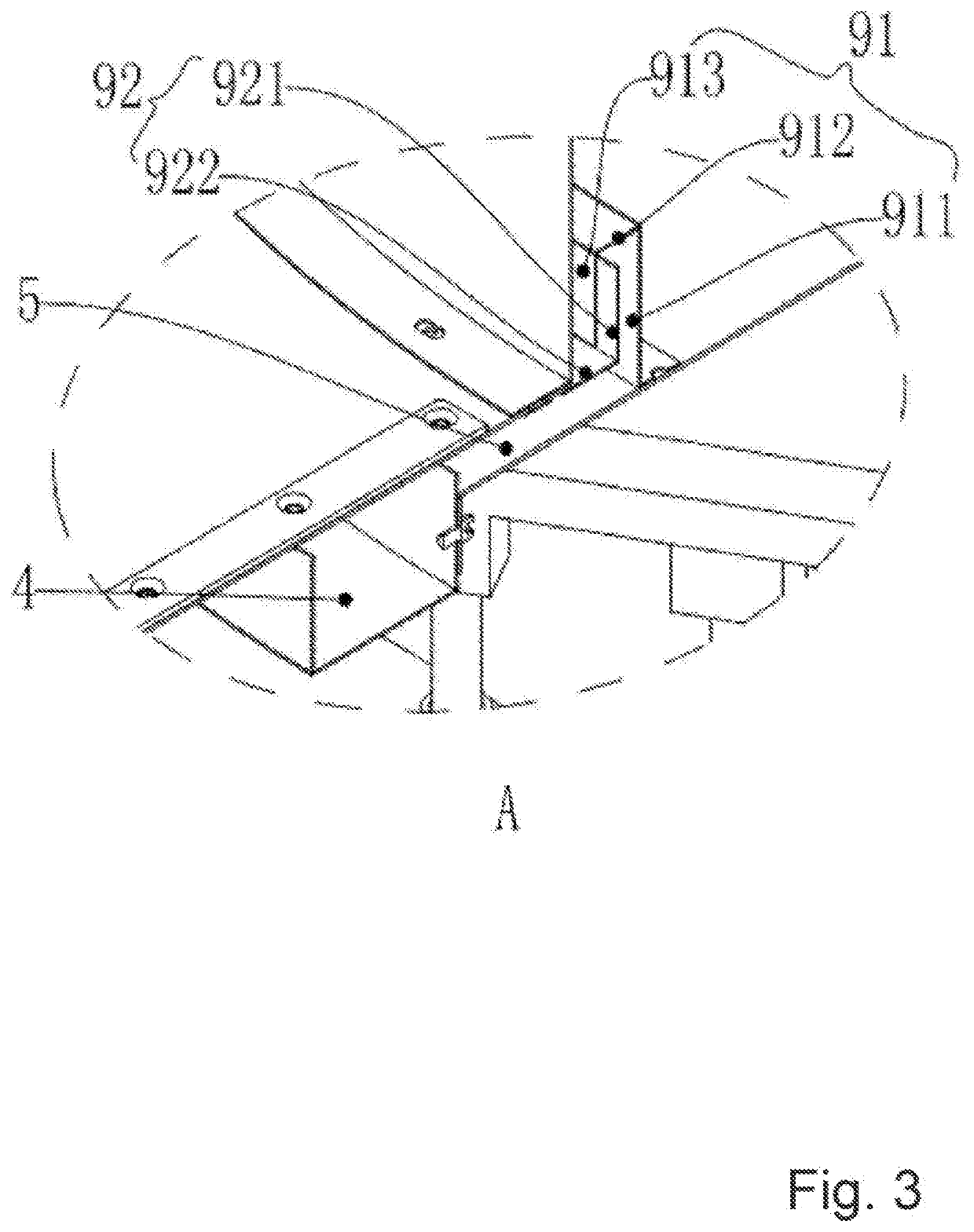
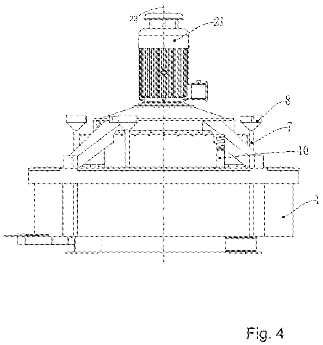
[0076]An artificial quartz stone mixer, includes a mixing barrel 1, a power transmission system 2, a mixing system 3 and a multi-section receiving trough 4. The power transmission system 2 is disposed above the mixing barrel 1. The mixing system 3 is disposed in the mixing barrel 1, and the power transmission system 2 is used to drive the mixing system 3 to move. Both ends of the receiving trough 4 are provided with notches, and multiple sections of the receiving trough 4 are provided on the top of the mixing barrel 1, and the ends of the adjacent two sections of the receiving trough 4 are spaced apart and do not contact each other.

[0077]After injecting ceramic powder, color material, etc. into the mixing barrel 1. The power transmission system 2 is started, so that the power transmission system 2 drives the mixing system 3 to agi...


PUM

PropertyMeasurementUnit
distanceaaaaaaaaaa
lengthaaaaaaaaaa
turning radiusaaaaaaaaaa

Abstract

A mixer for synthetic quartz includes a mixing barrel (1), a power transmission system (2), a mixing system (3), and multiple material receiving receptacles (4). The power transmission system is provided above the mixing tank. The mixing system is provided inside the mixing tank. The power transmission system is used to drive the mixing system to move. An opening is arranged at each of two ends of the material receiving receptacle. The multiple material receiving receptacles (4) are arranged at a top portion of the mixing tank, and end portions of two adjacent material receiving receptacles are spaced apart from each other without contact there between. A resin experiences low flow resistance in the material receiving receptacle, and thus can fall smoothly without accumulating in the material receiving receptacle. Moreover, the material receiving receptacle can be cleaned easily.

Description

[0001]The present application claims priority from and is a Track One PCT bypass continuation in part of PCT / CN2018 / 077366, filed Feb. 27, 2018 entitled Mixer For Synthetic Quartz by applicant Feizhou DENG, and by inventors harming QIU, Gao HE, and Qingguo ZHANG, now assigned to Veegoo Technology Co. Ltd., which was published as WO 2019 / 136804 Jul. 18, 2019 and claims priority from China application 201810034421.4 filed Jan. 15, 2018, the disclosure of which is incorporated herein by reference.TECHNICAL FIELD[0002]The invention relates to the technical field of mixing machinery, in particular to an artificial quartz stone mixer.BACKGROUND FIELD[0003]Artificial quartz stone has a hard texture (Mohs hardness 5-7) and a dense structure (density 2.5 g / cubic centimeter). It has the characteristics of wear resistance, pressure resistance, high temperature resistance, corrosion resistance and penetration resistance that other decorative materials cannot match. Artificial quartz stone is co...

Claims


Application Information

Patent Timeline
Patent Type & Authority Applications(United States)
IPC IPC(8): B01F7/00B28C7/10B28C5/12B28C5/14
CPCB01F7/00633B01F7/00308B28C7/10B28C5/1246B01F7/00325B28C5/147B01F2215/0047B28C3/00B28C7/04B01F27/0721B01F27/1121B01F27/82B01F27/95B01F35/189B01F35/71785B01F35/71731B01F27/191B01F27/1126B01F27/11252B01F2101/28
Inventor QIU, JIANPINGHE, GAOZHANG, QINGGUO
Owner VEEGOO TECH CO LTD
Learn More