Cyclonic vacuum cleaner

a cyclonic vacuum cleaner and cyclonic technology, applied in the direction of auxillary pretreatment, cleaning filter means, separation processes, etc., can solve the problems of reducing the efficiency of dirt separation, and achieve the effect of increasing the efficiency of cyclonic separation and being easy to empty

Inactive Publication Date: 2005-06-30
MIDEA AMERICA CORP
View PDF58 Cites 220 Cited by
  • Summary
  • Abstract
  • Description
  • Claims
  • Application Information

AI Technical Summary

Benefits of technology

[0008] The present invention involves a new cyclone separator design and method useful in vacuum cleaners and other cyclonic separators. The new design incorporates a slinger assembly disposed at the bottom of the cyclone separator. The slinger assembly increases the efficiency of cyclonic separation in a small space and substantially isolates the dirt collected in the dirt cup from the cyclonic chamber of the vacuum cleaner. This acts to prevent dirt collected in the dirt cup from becoming re-entrained in the working airstream. Moreover, in this way the interior of the dirt cup may be kept substantially free of any other structures, such as a second cyclone or a filter, so that the entire volume of the dirt cup may be used to collect and hold dirt and the dirt cup is easier to empty.

Problems solved by technology

In those systems, however, the dirt can some times become re-entrained in the suction airstream and so reduce the efficiency of dirt separation.

Method used


Image

  • Cyclonic vacuum cleaner
  • Cyclonic vacuum cleaner
  • Cyclonic vacuum cleaner

Examples


Embodiment Construction

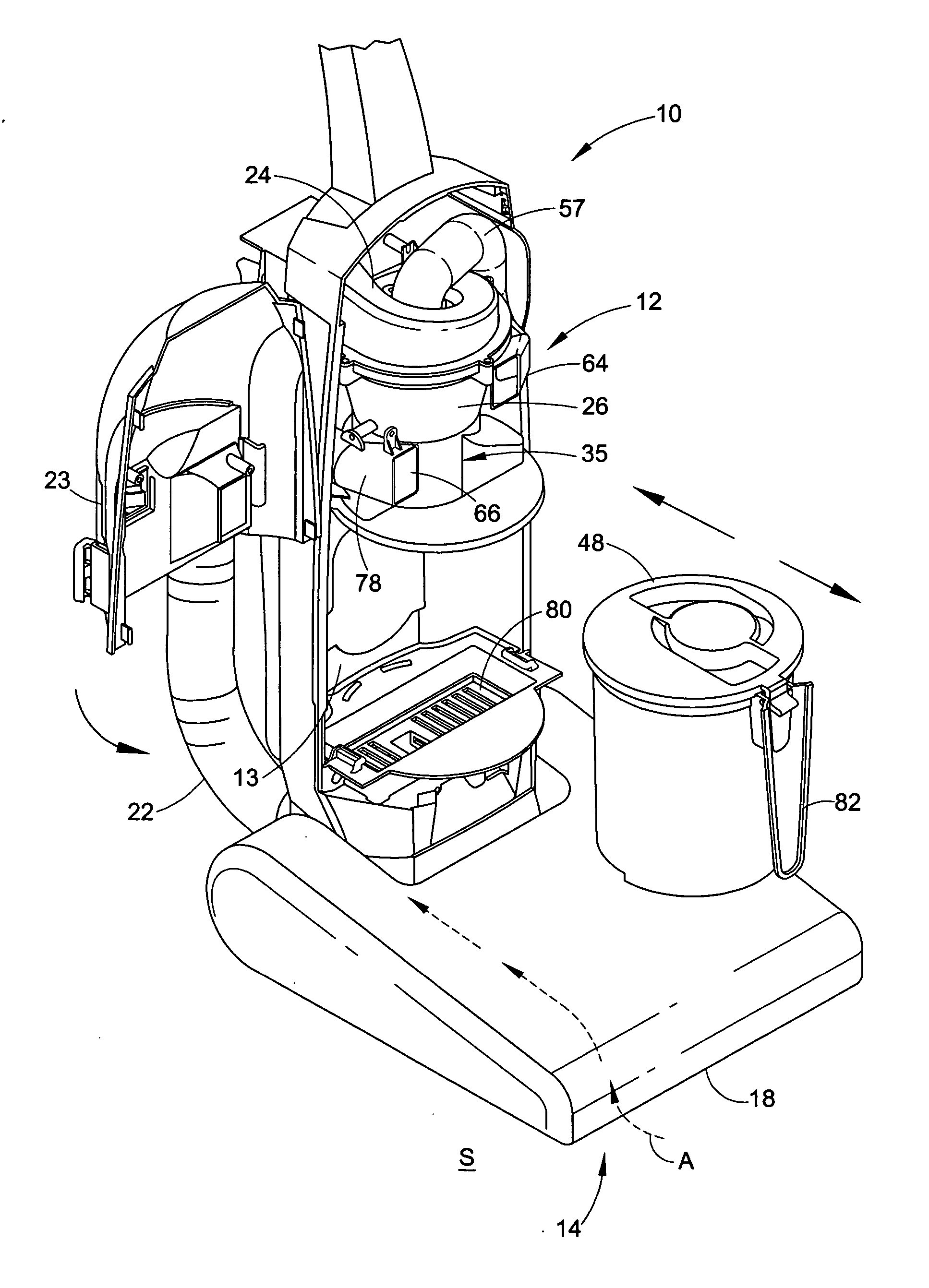
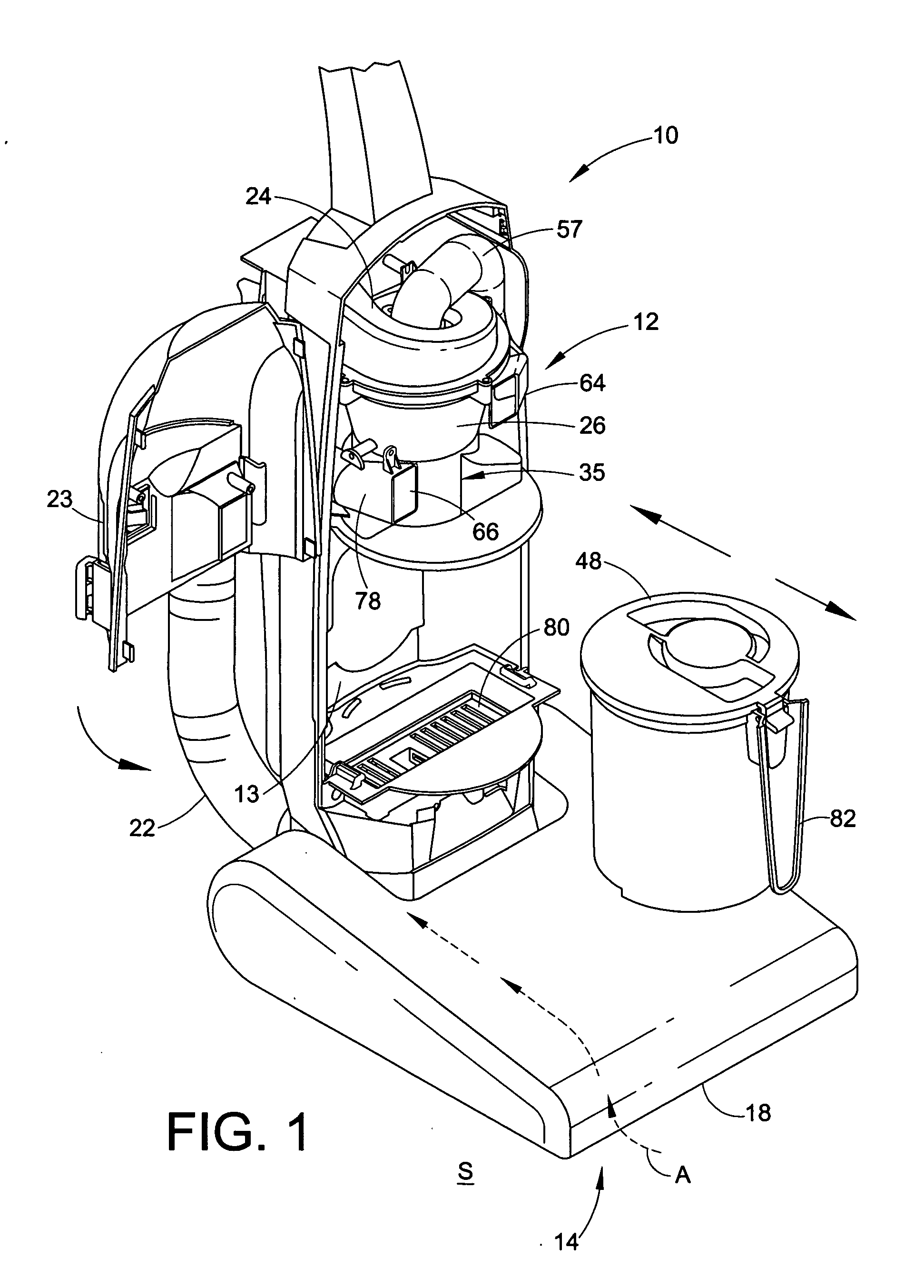
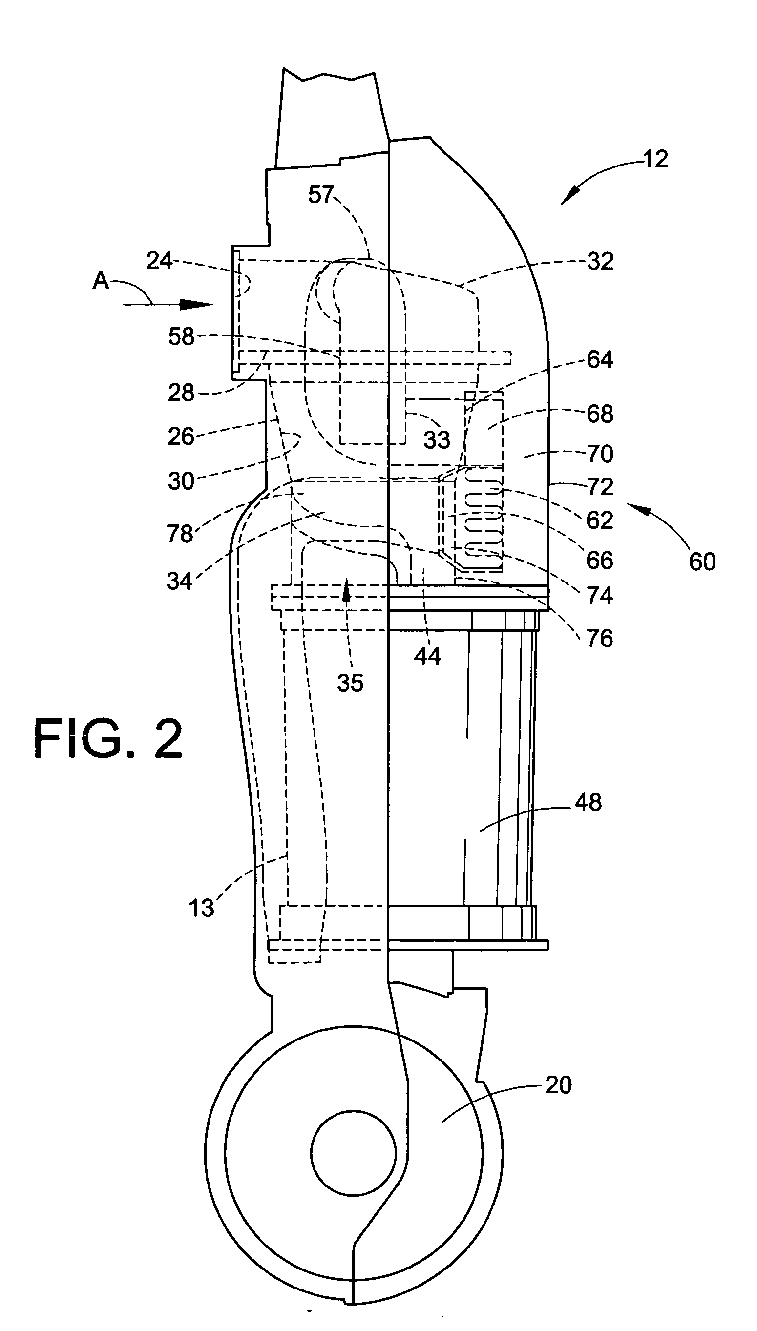
[0085] Referring now to the drawings in which like numerals designate like parts throughout the various views, preferred embodiments of a bagless cyclonic vacuum cleaner 10 are shown. FIG. 1 illustrates a vacuum cleaner 10 comprising an upright body 12 hingedly mounted to a base 14. The base 14 includes a nozzle opening 18 and wheels (not shown) for easy movement of the vacuum cleaner 10 over a surface S to be cleaned by pulling dirt and other debris into the nozzle opening 18. An airstream A is generated at the nozzle opening 18 by a motor and fan assembly 20 (FIG. 2), or some other suction generator. As it enters the nozzle opening 18 the airstream A is carrying dirt and other debris from the surface S to be cleaned. A brush roll may be disposed in or near the nozzle opening 18 to aid in removing dirt and debris from the surface S to be cleaned. The dirt and debris are thereafter filtered from the airstream A in one or more filtration stages, as described below. The Figures show a...


PUM

PropertyMeasurementUnit
structureaaaaaaaaaa
volumeaaaaaaaaaa
diameteraaaaaaaaaa

Abstract

A cyclonic vacuum cleaner includes a body portion, a nozzle portion and a dirt cup which is removable from the body portion. The dirt cup collects dirt and other debris separated by a cyclone and a cyclone slinger portion in the body portion. A main filter may be housed in a transparent filter door downstream of the cyclone. The dirt cup may be inserted into and sealingly held within the body portion by using a rotational camming structure.

Description

RELATED APPLICATION [0001] This application claims the benefit of U.S. Provisional patent application Ser. No. 60 / 492,498 filed on Aug. 5, 2003, the entire disclosure of which is hereby fully incorporated by reference.FIELD OF THE INVENTION [0002] The present invention concerns a cyclonic vacuum cleaner. In particular it concerns a structure and method whereby the efficiency of cyclonic separation of dirt from air may be enhanced. The structure and method have additional applicability to cyclonic separation outside of the vacuum cleaner field. BACKGROUND OF THE INVENTION [0003] Cyclonic separation systems in all types of vacuum cleaners, particularly but not exclusively bagless cleaners, are well known. Examples of cyclonic separation systems in upright cleaners include U.S. Pat. Nos. 6,026,540 to Wright, et al. and 5,078,761 to Dyson. Examples of cyclonic separation systems in canister cleaners include U.S. Pat. Nos. 5,248,323 to Stevenson, et al. and 5,080,697 to Finke, et al. Exa...

Claims


Application Information

Patent Timeline
Patent Type & Authority Applications(United States)
IPC IPC(8): A47L9/16B01D45/12
CPCA47L9/165A47L9/1658B01D45/12A47L9/1691A47L9/1683Y10S55/03
Inventor TANNER, MARKKONTIO, CHRISTERSEPKE, ARNOLDCHENOWETH, BRAD
Owner MIDEA AMERICA CORP
Why Eureka
Try Eureka