Electric operating apparatus for vehicle

a technology of electric operating apparatus and electric motor, which is applied in the direction of shock absorbers, servomotors, instruments, etc., can solve the problems of difficult to say that an appropriate braking force can always be obtained, the problem of electric braking operation apparatus and electric operating apparatus, etc., to achieve high fail safe function and appropriate braking force

Inactive Publication Date: 2008-09-16
TOYODA IRON WORKS CO LTD
View PDF31 Cites 20 Cited by
  • Summary
  • Abstract
  • Description
  • Claims
  • Application Information

AI Technical Summary

Benefits of technology

[0016]According to the thus structured electric operating apparatus for a vehicle, operational information concerning a requested operation of a driver and environmental information concerning a driving environment of a vehicle are detected, and a target pattern concerning the requested operation is set based on the environmental information, and a reaction force is controlled based on the operational information so that the requested operation is performed in accordance with the target pattern. Therefore, the requested operation can be easily performed in accordance with each target pattern in various driving environments, and a suitable (e.g., ideal) driving force or braking force corresponding to the target pattern is controlled in accordance with the requested operation, so that an excellent driving feeling can be easily obtained in various driving environments.
[0032]The damper device is to give a depression reaction force by the flow resistance of a fluid flowing through an orifice or the like, and a gas-type damper device that is filled with gas, such as air, as the fluid is suitably used. A damper device filled with a liquid, such as operating oil, or with another fluid may be employed. A check valve which blocks the flow of the fluid when the operational member is input and permits the flow of the fluid when the operational member is returned can be provided, so that large flow resistance is generated by the orifice or the like when the operational member is depressed, and small flow resistance is generated so that the operational member can be quickly returned to its original position by the spring member or the like when the operational member is returned.

Problems solved by technology

The thus structured electric operating apparatus has a conventional problem in the fact that a driver accustomed to a conventional mechanical operating apparatus has difficulty in depressing a pedal because a depression reaction force is hardly generated by depressing the pedal although a reaction force is generated and applied by a return spring.
However, in these conventional reaction force apparatuses, a reaction force is merely changed in accordance with a situation in which an operational member is operated, for example, in accordance with depressing speed, and no consideration is given to driving environments, such as road conditions, weather conditions, vehicular traveling speed conditions, and vehicle conditions, excluding a braking operation.
Therefore, it is difficult to say that an appropriate braking force can always be obtained under various driving environments, and there is still room for improvement in allowing an easy operation so that even an inexperienced driver can always obtain an appropriate braking force.
This problem exists not only in an electric braking operation apparatus but also in an electric operating apparatus, such as an accelerator pedal, for traveling requirements.

Method used


Image

  • Electric operating apparatus for vehicle
  • Electric operating apparatus for vehicle
  • Electric operating apparatus for vehicle

Examples


embodiments

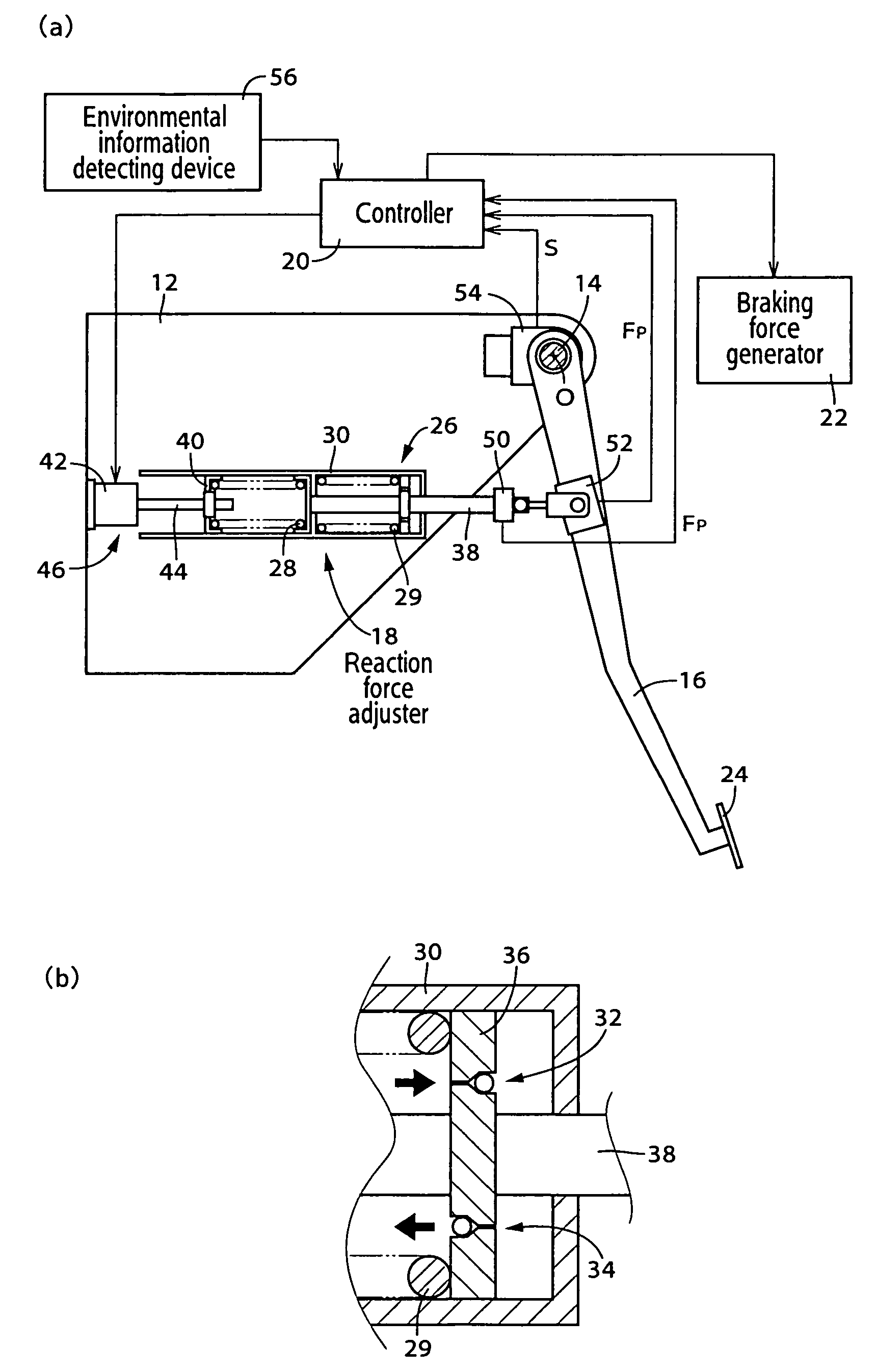
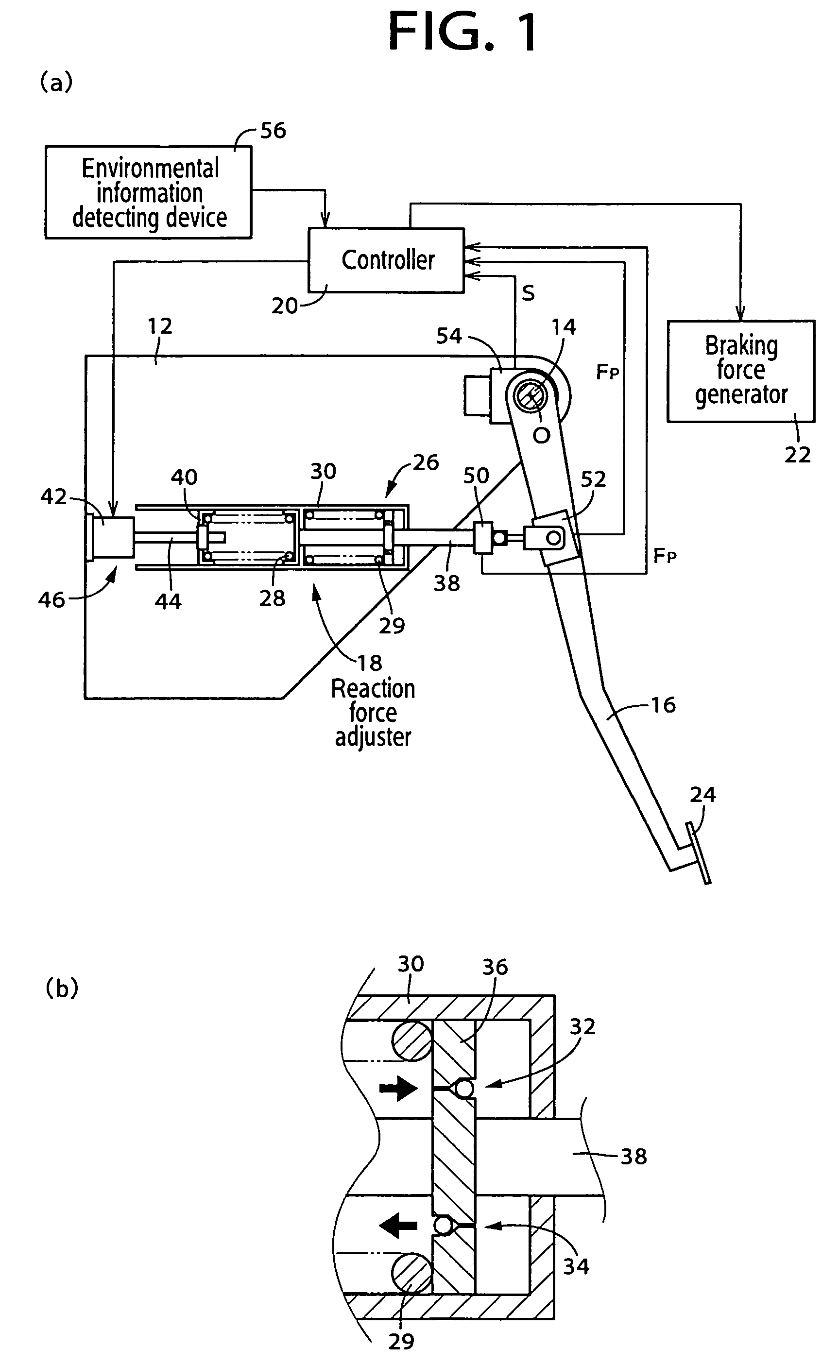
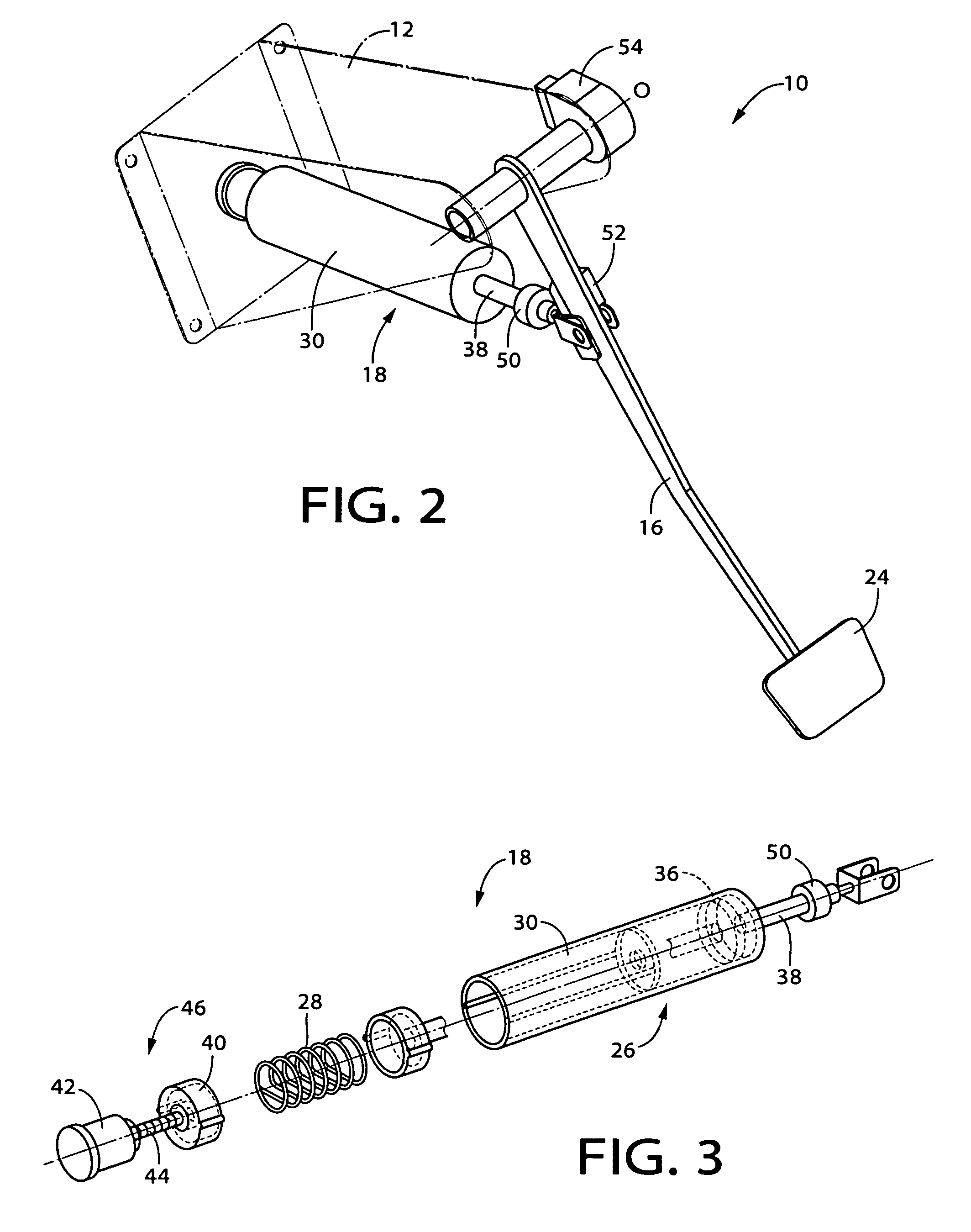
[0057]Embodiments of the present invention will be hereinafter described in detail with reference to the drawings. FIG. 1 shows an electric service brake operating apparatus 10 for a vehicle (hereinafter, referred to simply as “brake operating apparatus 10”), which is an embodiment of the present invention. FIG. 1(a) is a schematic block flow diagram of the apparatus whose part is sectionally shown, and FIG. 1(b) thereof is a sectional view of a damper portion. The brake operating apparatus 10 includes an operation pedal 16 rotatably disposed around an axis center O of a substantially horizontal supporting shaft 14 provided in a bracket 12 fixedly integral with a vehicle body, a reaction force adjuster 18, a controller 20, and a braking force generator 22. The operation pedal 16 is a brake operating member that is depressed by a driver in accordance with a braking request. A depression part (pad) 24 is provided at the lower end of the operation pedal 16. FIG. 2 is a perspective view...


PUM


Abstract

An electric operating apparatus for a vehicle including an operational member operated in accordance with a traveling request or a braking request of a driver; and a reaction force adjuster that can electrically adjust a reaction force of the operational member; and wherein a driving force or a braking force is electrically controlled in accordance with a requested operation applied to the operational member against the reaction force; comprises (a) an operational information detecting device for detecting operational information concerning a requested operation applied to the operational member by the driver; (b) an environmental information detecting device for detecting environmental information concerning a driving environment of the vehicle; (c) a target pattern setting means for setting a target pattern concerning the requested operation based on the environmental information; and (d) a driving support means for controlling the reaction force adjusted by the reaction force adjuster based on the operational information so that the requested operation is performed in accordance with the target pattern.

Description

[0001]This application is based on Japanese Patent Application No. 2004-130381 filed Apr. 26, 2004, the contents of which are incorporated hereinto by reference.BACKGROUND OF THE INVENTION[0002]1. Field of the Invention[0003]This invention relates to an electric operating apparatus for a vehicle, and more particularly to an electric operating apparatus for a vehicle in which a requested operation, such as a braking operation, is performed in accordance with a target pattern.[0004]2. Discussion of Related Art[0005]An electric operating apparatus for a vehicle in which a hydraulic power unit, an electric motor, etc., are operated in a predetermined manner by electrically detecting the depressing stroke of an operation pedal has been proposed, for example, in a service brake pedal apparatus used in a vehicle. The thus structured electric operating apparatus has a conventional problem in the fact that a driver accustomed to a conventional mechanical operating apparatus has difficulty in...

Claims


Application Information

Patent Timeline
Patent Type & Authority Patents(United States)
IPC IPC(8): B60K31/00B60T7/02B60T7/04B60T7/06B60T8/32F16F9/32F16F9/46F16F15/023G05G1/30G05G1/38G05G5/03
CPCB60T7/042
Inventor FUJIWARA, NOBORUHAYASHIHARA, TAKASHIISONO, HIROSHI
Owner TOYODA IRON WORKS CO LTD
Why Eureka
Try Eureka