Tubulation and/or sepcial-section tubulation reforced heat exchange tube

A technology for heat exchange tubes and tube sections, which is applied in the field of enhanced heat exchange tubes with special-shaped/shaped cross-sections of tube sections and/or tube sections, which can solve the requirements of increased cleaning and maintenance workload, increased flow resistance or power consumption, and fluid cleanliness Very strict and other problems, to achieve the effect of heat transfer enhancement, reduce vibration, and easy to clean

Inactive Publication Date: 2003-11-12
TSINGHUA UNIV
View PDF0 Cites 20 Cited by
  • Summary
  • Abstract
  • Description
  • Claims
  • Application Information

AI Technical Summary

Problems solved by technology

Although the existing technology has obvious effects in enhancing heat transfer, there are also shortcomings: first, some intensified tubes increase flow resistance or power consumption while enhancing heat transfer. Therefore, from the perspective of effective energy utilization Seeing that the income is not large, the second is that the manufacturing cost of some reinforced tubes has increased so much that the economic benefits are not obvious enough
In addition, the first method has strict requirements on the cleanliness of the fluid, which increases the workload of cleaning and maintenance

Method used


Image

  • Tubulation and/or sepcial-section tubulation reforced heat exchange tube
  • Tubulation and/or sepcial-section tubulation reforced heat exchange tube
  • Tubulation and/or sepcial-section tubulation reforced heat exchange tube

Examples


Embodiment 1

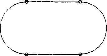
[0046] Figure 9 It is a schematic structural view of the regular shaped tube in embodiment 1. The entire normal-shaped pipe consists of a deformed pipe section 1, an oval pipe section 2, a transition pipe section 3 and a round pipe section 4; Figure 9 From left to right, the four basic pipe sections follow the rules of "circular pipe section - transitional pipe section - elliptical pipe section - positive deformation pipe section - elliptical pipe section - positive deformation pipe section - elliptical pipe section - transitional pipe section - circular pipe section—…" The sequence is arranged periodically, and the deformed pipe section and the elliptical pipe section are the main body of heat exchange. During implementation, the number of circular pipe sections can be increased or decreased according to the requirements of the compressive strength of the pipe, and the circular pipe sections can be arranged in other appropriate positions according to the needs of installin...

Embodiment 2

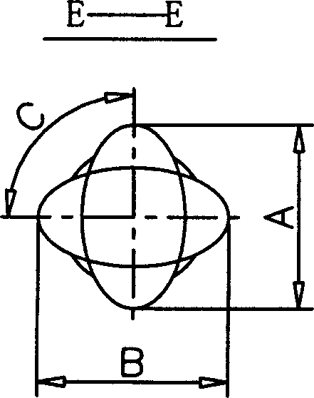
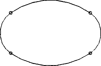
[0049] Figure 11 It is a structural schematic diagram of the deviation-shaped tube of Example 2. The whole deformed pipe consists of a deformed pipe section 1, an oval pipe section 2, a transition pipe section 3 and a round pipe section 4. The four basic pipe sections are periodically arranged in the order of "round pipe section—transition pipe section—elliptical pipe section—deformed pipe section—elliptical pipe section—deformed pipe section—elliptical pipe section—transition pipe section—circular pipe section—…". The entire deviation-shaped pipe is made of a base pipe with an inner diameter d after rolling or molding, and can also be formed at one time when rolling a seamless pipe. The length Lo of the circular pipe section, the length Lt of the transition pipe section, the length Lr of the deflected pipe section, and the length Le of the elliptical pipe section are the same as those of the normal shaped pipe. The cross-sectional shape of the elliptical pipe segment is a ...


PUM


Abstract

The heat exchange tube comprises of tabulations with different sections: circular tube (base tube), elliptical tube section, oblateness tube section, egg-shaped tube section, the half moon tube section, triangle tube section, transformation tube section and transition tube section. The strengthened heat exchange tube comprises at least three of above said tube sections with other five tube sections being assorted. The different sections can be combined randomly or arranged according to following sequence periodically: circular tube - transition tube - elliptical tube (or oblateness tube, egg-shaped tube, half moon tube, triangle tube) - transformation tube - elliptical tube (or oblateness tube, egg-shaped tube, etc.) - transformation tube - elliptical tube, ect. The combined tube strengthens heat exchange 30-500% but the flow resistance is only raised 20-100%. The invented tube possesses the advantages of not easy of scaling, easy of cleaning and reducing vibration.

Description

technical field [0001] The pipe section and / or the section of the pipe section is shaped / shaped enhanced heat exchange tube, which belongs to the technical field of enhanced heat exchange and heat exchanger. Background technique [0002] Shell and tube heat exchangers (including sleeve and tube heat exchangers) are one of the most widely used heat exchangers in the heat exchanger family. Although it has a long history and relatively old technology, it is still used in petroleum, chemical, power and other industries because of its relatively simple manufacturing technology, easy access to materials, relatively low cost, and its ability to adapt to high temperature and high pressure conditions. widely used in the sector. On the other hand, people are also making continuous efforts to improve it, especially inventing various enhanced heat exchange tubes instead of ordinary round tubes to manufacture shell-and-tube heat exchangers to overcome its low heat exchange efficiency, l...

Claims


Application Information

Patent Timeline
Patent Type & Authority Applications(China)
IPC IPC(8): F28F1/02
Inventor 孟继安过增元胡桅林李志信
Owner TSINGHUA UNIV
Why Eureka
Try Eureka