Packet transfer apparatus and method

Active Publication Date: 2006-05-09
NEC CORP
View PDF5 Cites 14 Cited by
  • Summary
  • Abstract
  • Description
  • Claims
  • Application Information

AI Technical Summary

Benefits of technology

[0016]It is an object of the present invention to provide a packet transfer apparatus and m

Problems solved by technology

However, data transmission/reception via a wide area network suffers a transfer path which cannot always use a large MTU due to restrictions by data link specifications or problems caused by the physical channel quality.
The physical qualities of these media are not so high, which makes it difficult to adopt a large MTU.
The processing load greatly increases, and this method is not employed for a high-traffic relay.
However, the packet length actually transferred through a network is determined by the smallest MTU among MTUs supported by transfer

Method used


Image

  • Packet transfer apparatus and method
  • Packet transfer apparatus and method
  • Packet transfer apparatus and method

Examples


first embodiment

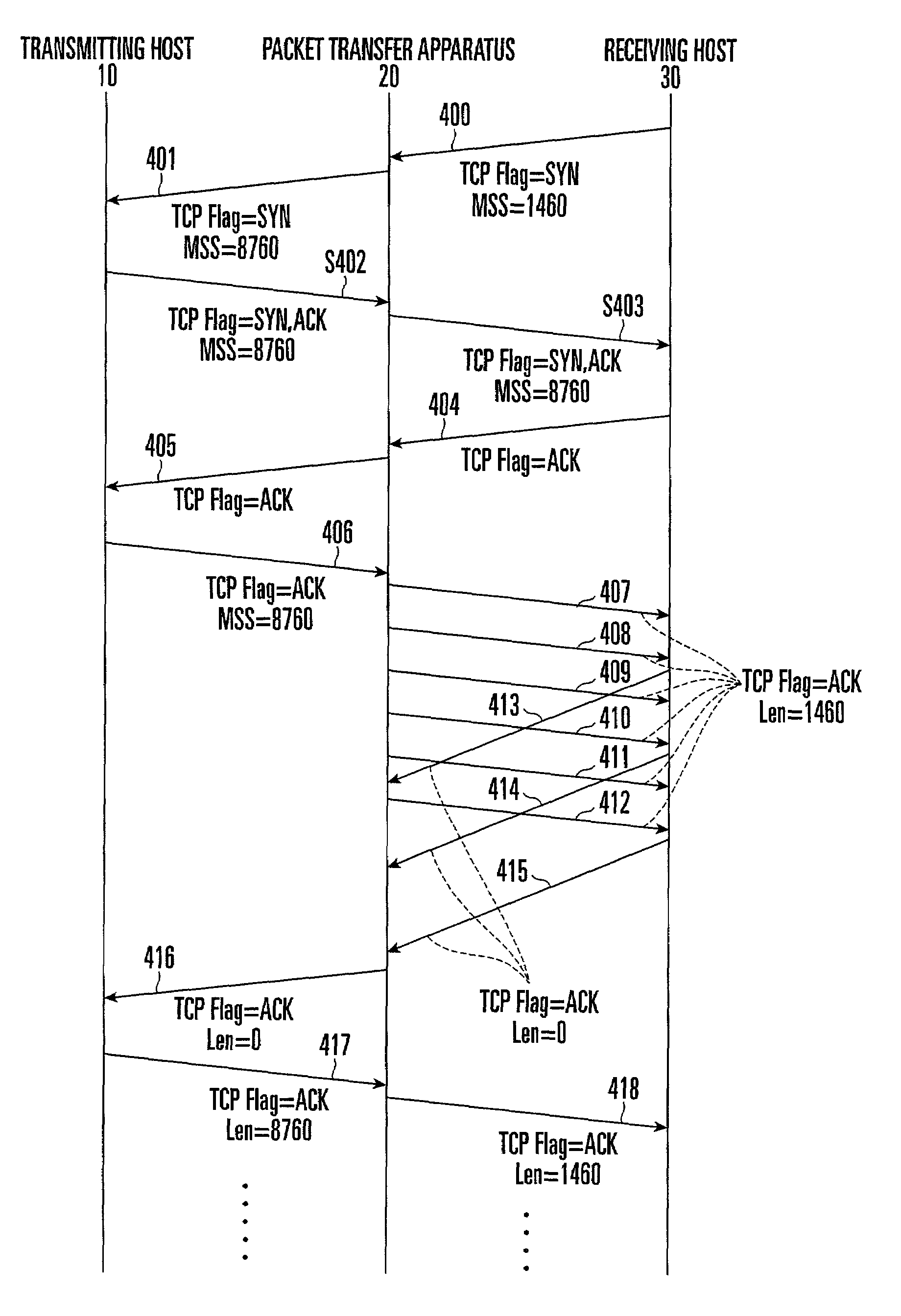
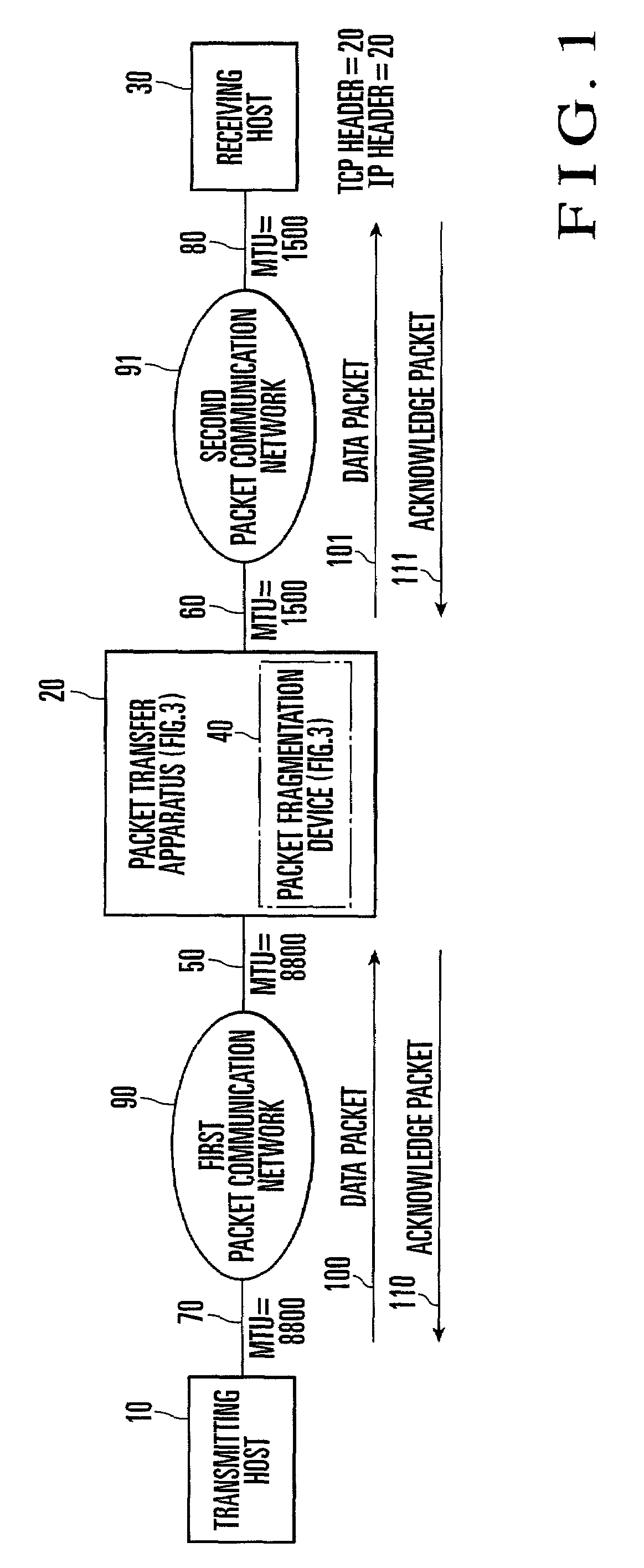
[0036]FIG. 1 shows a network to which a packet transfer apparatus according to the present invention is applied. A transmitting hosts 10 is connected to a first packet communication network 90 via a third data link 70. A packet transfer apparatus 20 is connected to the first packet communication network 90 via a first data link 50, and to a second packet communication network 91 via a second data link 60. A receiving hosts 30 is connected to the second packet communication network 91 via a fourth data link 80.

[0037]A data packet 100 output from the transmitting hosts 10 is fragmented by a packet fragmentation device 40 installed in the packet transfer apparatus 20, and transferred as a data packet 101 to the receiving hosts 30. The receiving hosts 30 receives the data packet 101 from the packet transfer apparatus 20. Then, the receiving hosts 30 outputs an acknowledge packet 111, and the packet transfer apparatus 20 transfers an acknowledge packet 110 to the transmitting hosts 10.

[0...

second embodiment

[0084]In the second embodiment, an ICMP unreachable packet is input from a network on the receiving hosts 30 side, and data fragmentation is requested. At this time, if an MSS value obtained from the MTU value of the next-hop network is equal to or larger than the MSS used between the transmitting hosts 10 and the packet transfer apparatus 21, only the segment size used between the receiving hosts 30 and the packet transfer apparatus 21 is decreased, and the input ICMP unreachable packet is not transferred to the transmitting hosts.

[0085]If the MSS value obtained from the MTU value of the next-hop network is smaller than the MSS used between the transmitting hosts 10 and the packet transfer apparatus 21, the MSS value used between the transmitting hosts 10 and the packet transfer apparatus 21 must be changed. Thus, the received ICMP unreachable packet is directly transferred to the transmitting hosts.

[0086]Even upon generation of an ICMP unreachable packet based on path MTU discover...

third embodiment

[0088]the present invention will be described with reference to FIG. 8.

[0089]In a packet fragmentation device 42 shown in FIG. 8, a registered host address holding unit 331 holds a host address set outside a packet transfer apparatus 20 or a pair of host addresses, and corresponding MSSs. When a connection identification unit 330 detects a new connection, the registered host address holding unit 331 checks whether this connection is a connection to a registered host address.

[0090]If the connection is not a connection to a registered host address, the registered host address holding unit 331 does not execute packet fragmentation. If the connection is a connection to a registered host address, the registered host address holding unit 331 notifies the connection identification unit 330 of a corresponding MSS so as to perform packet fragmentation.

[0091]For example, data links directly connected to the packet transfer apparatus 20 and a transmitting hosts 10 support an MTU as large as ab...


PUM


Abstract

A packet transfer apparatus includes an MSS option rewrite unit and packet fragmentation unit. The MSS option rewrite unit determines a first maximum segment size used in a transport layer between a transmitting hosts and the packet transfer apparatus on the basis of path information between the transmitting hosts and the packet transfer apparatus, and notifies the transmitting hosts of the first maximum segment size. The MSS option rewrite unit determines a second maximum segment size used in a transport layer between a receiving hosts and the packet transfer apparatus on the basis of path information between the receiving hosts and the packet transfer apparatus, and notifies the receiving hosts of the second maximum segment size.

Description

BACKGROUND OF THE INVENTION[0001]The present invention relates to a packet transfer apparatus and method for performing routing of a variable-length packet on the basis of TCP / IP (Transmission Control Protocol / Internet Protocol).[0002]In packet communication based on TCP / IP, a host for transmitting data generally fragments data into small units called packets. Then, the host adds header information such as a transmission source address or destination address to each packet, and sends the resultant packet to a network. At this time, the maximum packet length transmittable from each host to a network is determined by MTU (Maximum Transmission Unit) supported by the protocol of the data link layer (second layer of an OSI reference model) of a network connected to a host for exchanging data.[0003]For example, the MTU value used in major data link layer protocols is 1,500 bytes for Ethernet whose transmission rate is 10 / 100 Mbps, and 4,352 bytes for FDDI (Fiber Distributed Data Interface...

Claims


Application Information

Patent Timeline
IPC IPC(8): H04L12/28G06F15/173H04J3/26H04J3/00H04L12/66H04L47/36H04L47/43
CPCH04L29/06H04L45/38H04L45/60H04L47/10H04L47/27H04L69/163H04L47/36H04L69/166H04L69/161H04L47/323H04L69/16H04L47/43H04L9/40
Inventor MATSUNAGA, YASUHIKO
Owner NEC CORP
Why Eureka
Try Eureka