Crash-active headrest

a headrest and active technology, applied in the field of headrests, can solve the problems of saving labor costs, and achieve the effects of simple and cost-effective production, improved comfort, and simple headrest mobility

Inactive Publication Date: 2006-07-04
KEIPER GMBH & CO KG
View PDF50 Cites 71 Cited by
  • Summary
  • Abstract
  • Description
  • Claims
  • Application Information

AI Technical Summary

Benefits of technology

[0005]The headrest system is stabilized by the upper and lower linkages being unparallel, i.e. by means of the four-bar linkage not being a parallelogram. With this, one avoids a dead center in the four-bar linkage in the initial position, which might prevent the four-bar linkage from coming out in the event of a crash. In addition, the relevant lever acting on the linkages under the impact of forces coming from the front or from above, can thus be kept short. Finally, a more favorable capture angle can also be achieved. Preferably, all this is achieved by a difference in the length of the linkages, for example by making the lower linkages longer than the upper linkages as defined between the respective joints in the four-bar linkage. The long lower linkages also have the advantage that when the four-bar linkage comes out, the upholstered part of the impact element moves mainly at a tangent with respect to the direction of travel towards the front, this arrangement allowing a simpler covering and preventing collisions in the lower area.
[0013]Preferably, the restraint element is embedded over a large area in the impact element so as to ensure a large-area force transfer and reduced pressure on surfaces. Preferably, the impact element has a receptacle for the restraint element in which the restraint element, preferably having a crooked middle area, can be embedded (e.g., fitted into) positively and can be closed with a lid. The energy storage device, preferably in the form of a spring, preferably bears directly on the restraint element that is preferably made of metal, so as to avoid any high surface pressure between the metal and the plastic.

Problems solved by technology

Preferably, the passenger can reset the headrest himself, which again saves labor costs.

Method used


Image

  • Crash-active headrest
  • Crash-active headrest
  • Crash-active headrest

Examples


Embodiment Construction

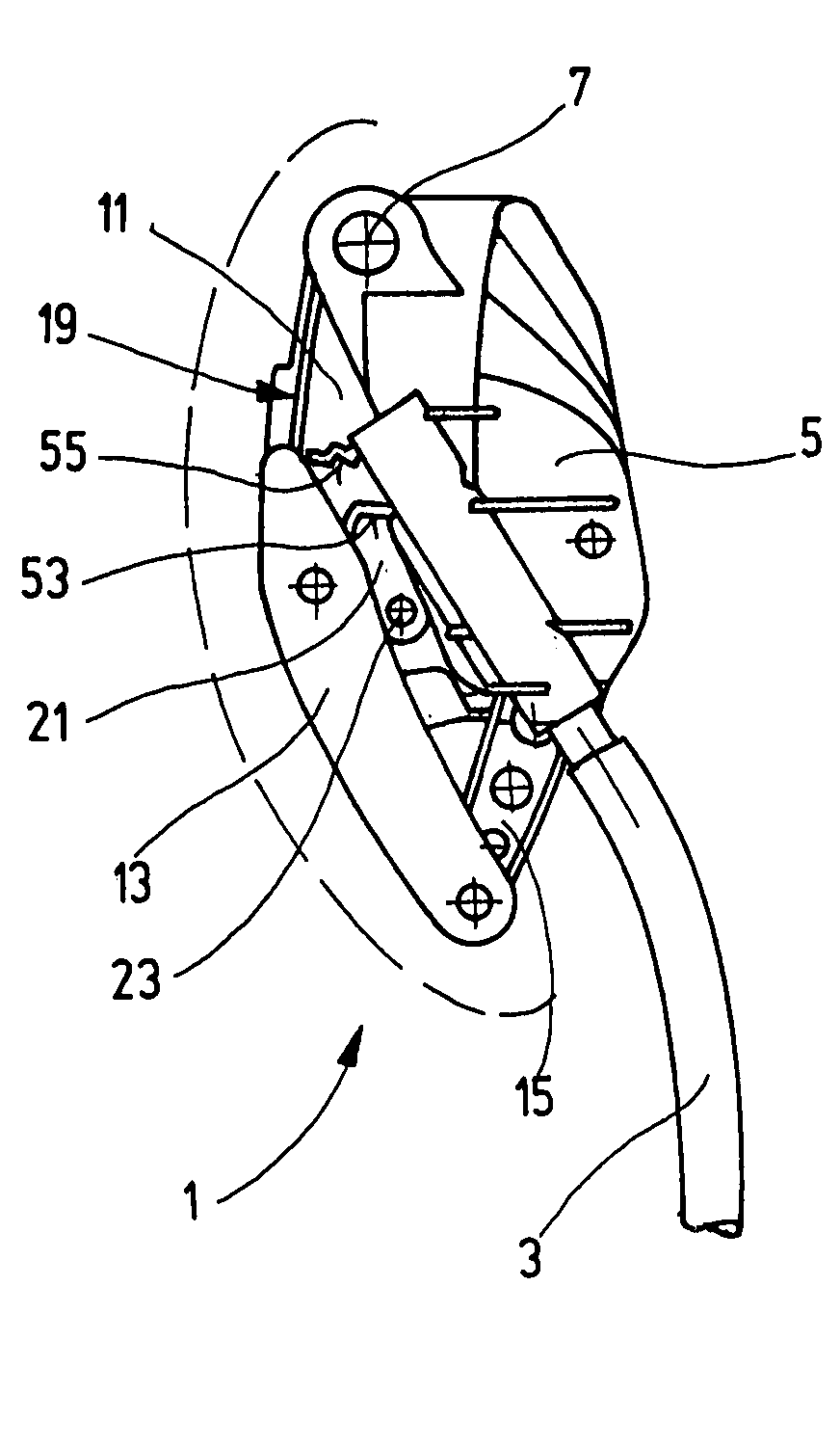
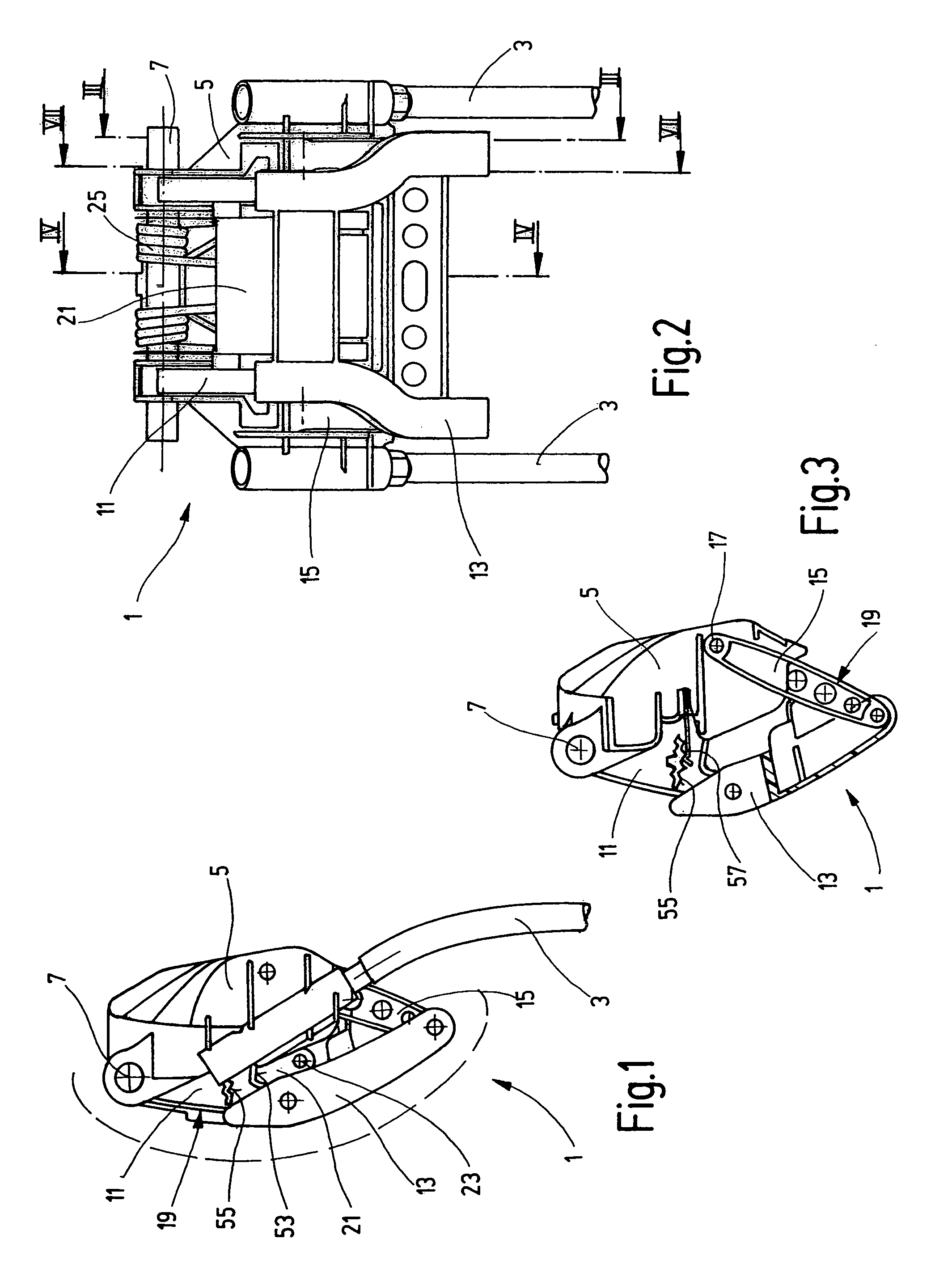
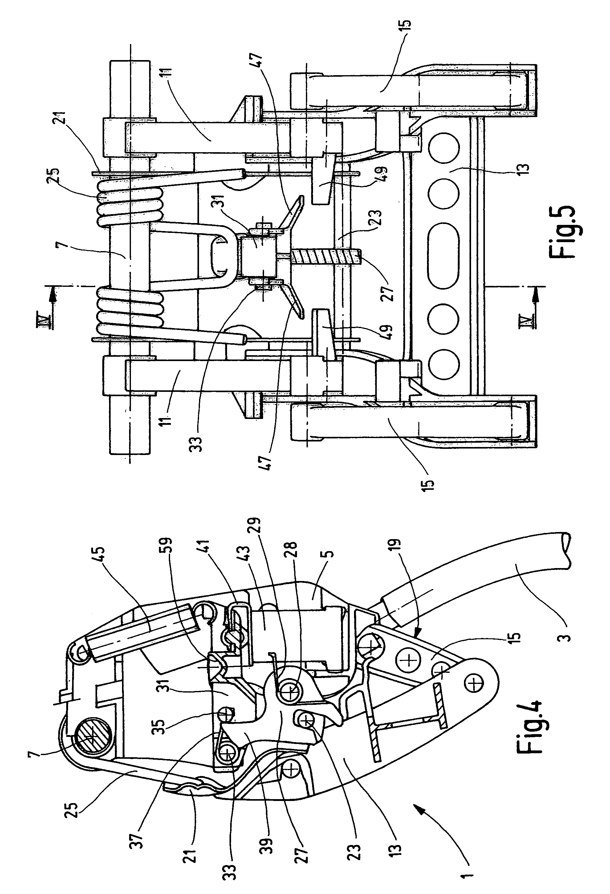
[0037]The first exemplary embodiment has a headrest 1 for a vehicle seat of an automobile. The height of the headrest 1 can be adjusted by means of two parallel headrest bars 3 that are movably held in the backrest of the vehicle seat. The headrest bars 3 are firmly inserted with their upper end in a carrier 5 that is arranged transversally to the head rest bars 3. A horizontally arranged axle 7 running transversally to the head rest bars 3 is borne in the upper end of the carrier 5.

[0038]A pair of upper linkages 11 is pivotably borne on the axle 7. The upper linkages 11 are at a distance from one another and each has an approximately triangular shape. The axle 7 is arranged in a corner of each upper linkage 11. The upper linkages 11 are parallel to one another, pointing frontward and downward. In the frontmost corner of each upper linkage 11, the linkage is linked to the upper end of an impact element 13, which is arranged in front of the carrier 5 (with respect to the direction of...


PUM


Abstract

In a headrest (1) for a vehicle seat, having a carrier (5), at least one upper and lower linkage (11, 15) linked to the carrier (5), which can be pivoted around horizontal axles (7, 17), a impact element (13) linked to the linkages (11, 15) which forms at least one four-bar linkage (19) with the linkages (11, 15) and the carrier (5), and an energy storage device (25), the energy storage device (25) driving the four-bar linkage (19) in the event of a crash, so that the impact element (13) comes out forward from an original position into a crash position that is locked against a backward movement by a crash lock, the upper linkage (11) and the lower linkage (15) are unparallel with respect to one another.

Description

CROSS-REFERENCE TO RELATED APPLICATION[0001]The present application is a continuation of PCT / EP03 / 013757, which was filed Dec. 5, 2003, and is incorporated herein by reference, in its entirety.BACKGROUND OF THE INVENTION[0002]The present invention relates to a headrest for a vehicle seat, with the headrest including a four-bar linkage having upper and lower linkages mounted for pivoting relative to a carrier, and an impact element that is connected to the upper and lower linkages so that the impact element moves from an original position to a crash position by moving away from the carrier in an at least generally forward direction in response to pivoting of the upper and lower linkages; an energy storage device for driving the four-bar linkage so that the impact element moves from the original position to the crash position in response to a crash; and a crash lock for restricting the impact element from moving from the crash position toward the original position.[0003]A headrest of ...

Claims


Application Information

Patent Timeline
Patent Type & Authority Patents(United States)
IPC IPC(8): B60N2/42B60N2/48
CPCB60N2/4861B60N2/4885B60N2/4864B60N2/862B60N2/865B60N2/888B60N2/42
Inventor SCHILLING, JURGENBOHMER, MICHAELHIPPEL, DANIELWROBEL, DARIUSKLEIN, HARALDRUESS, GEORGRIHLMANN, ALI PETER
Owner KEIPER GMBH & CO KG
Why Eureka
Try Eureka