Sensitive fluid balancing relief valve

a fluid balancing and sensitive technology, applied in the direction of fluid pressure control, process and machine control, instruments, etc., can solve the problems of complex spring and seal mechanism, large variation in relieving pressure, and clear failure to meet the dynamic set-point requirement desired in the art. , to achieve the effect of simple and clean

Inactive Publication Date: 2006-07-25
JENNINGS JEFFREY D
View PDF5 Cites 12 Cited by
  • Summary
  • Abstract
  • Description
  • Claims
  • Application Information

AI Technical Summary

Benefits of technology

[0011]It is an object of the invention to provide a pressure relief device which is simple and cleanable, making it useful in a variety of process applications where debris, freezeable product, or sanitary requirements prohibit recesses or crevices.
[0013]Particular features of the relief device include, simplicity and cleanability, response to remote reference signal and high sensitivity to slight differences between the reference pressure and process pressure to achieve complete balance between vessel and reference pressure.
[0016]Yet another objective of the invention is to provide a device with high pressure sensitivity, while preventing the unnecessary venting of process fluids. This invention is imminently suitable for protecting sensitive instrumentation from moisture, foam or debris from the vessel venting process.

Problems solved by technology

Typical diaphragm relief valves, such as those exemplified in U.S. Pat. No. 5,944,050, do present simple, cleanable surfaces yet they clearly do not meet the dynamic set-point requirement desired in the art.
Furthermore, the inaccuracies of the spring compression typically result in wide variations in relieving pressures, often greater than 10%, and the variations change over time.
These typically involve complex spring and seal mechanisms.
Besides the inherent robustness issues with the complex mechanisms, they are clearly not acceptable for use in processes with debris, freezeable product, or requiring cleanability.
Typical relief valves are quite insensitive to slight differences in pressure, and typically have large cracking pressure biases.
Typically available pilot actuated relief valves cannot control vessel pressure to the exact pressure of the reference signal.

Method used


Image

  • Sensitive fluid balancing relief valve
  • Sensitive fluid balancing relief valve
  • Sensitive fluid balancing relief valve

Examples


Embodiment Construction

[0025]The invention is described with reference to the drawings. The drawings are provided to facilitate discussion of the invention and are not intended to limit the invention in any way. In the drawings all similar elements are numbered accordingly.

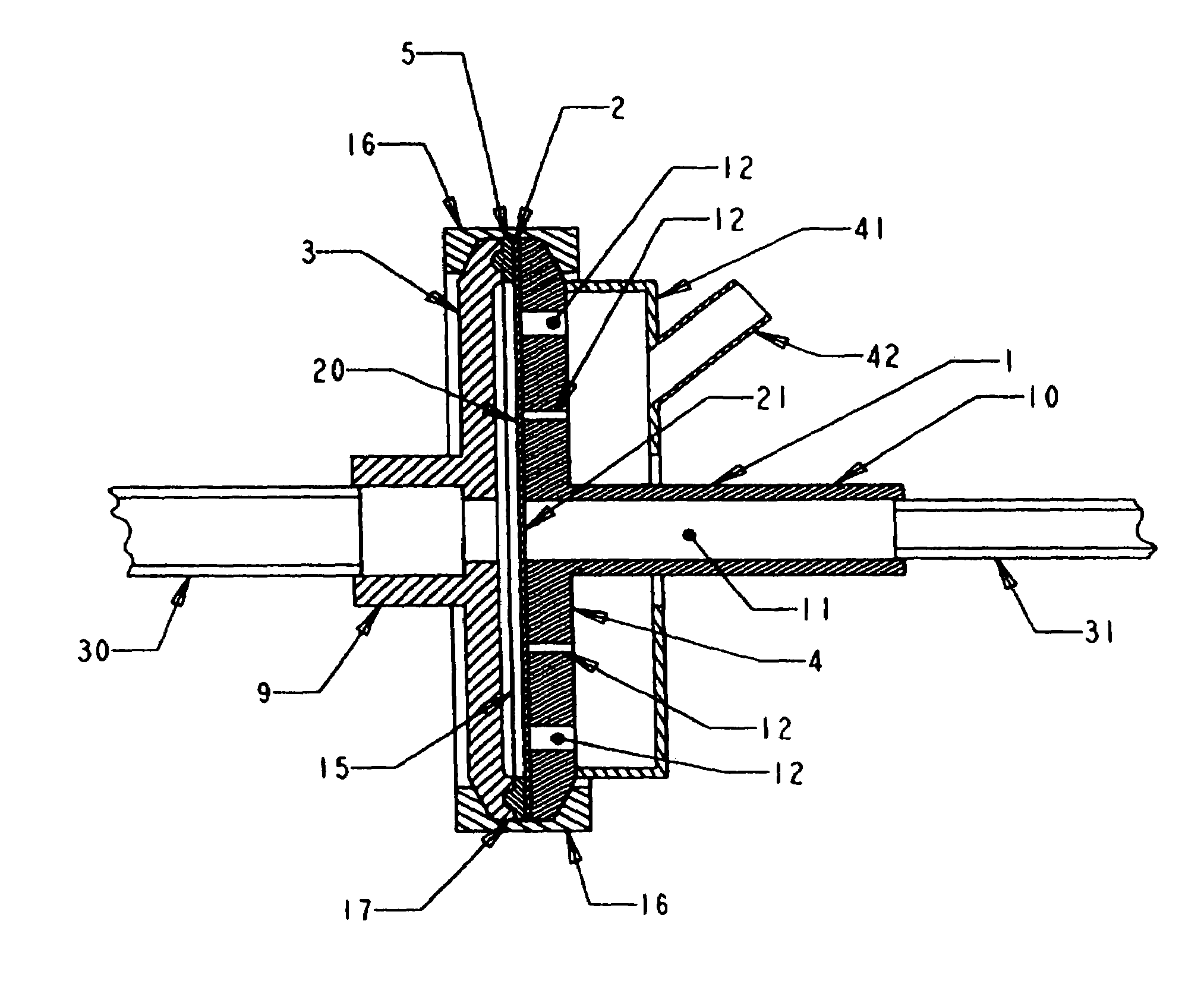
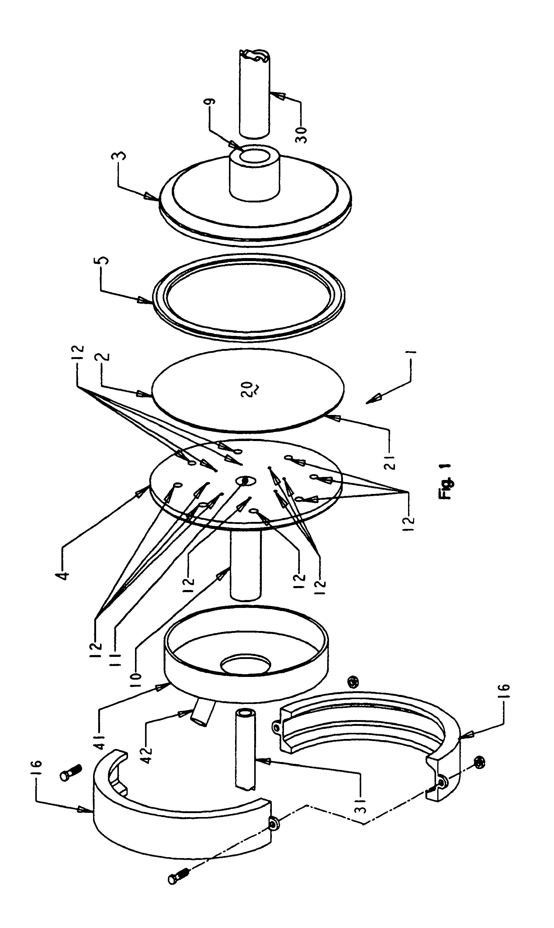
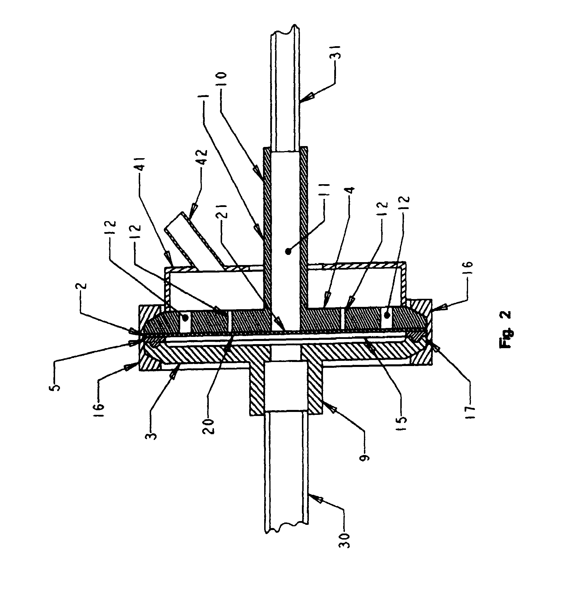
[0026]An embodiment of the present invention is provided in FIG. 1. In FIG. 1, the modulated pressure relief valve, generally represented at 1, is shown in exploded perspective view. The modulated pressure relief valve, 1, comprises a diaphragm, 2, which is enclosed between a reference housing, 3, and a process housing, 4. The diaphragm, 2, comprises a reference surface, 20, and a process surface, 21, which is opposite the reference surface. For the purposes of the present application the volume between the reference surface of the diaphragm and reference housing is referred to as the reference volume and the area between the process surface of the diaphragm and the process housing is referred to as the process volume. An optional seal,...


PUM


Abstract

A relief valve comprising a diaphragm for control of process pressure is provided. The diaphragm has a fluid pressure on a first side and a process pressure on a second side. The second side is engagable with a process void and at least one vent void such that when the process pressure is below the fluid pressure the diaphragm is engaged with the vent void. When the process pressure is above the fluid pressure the diaphragm is not engaged with the vent void.

Description

CROSS-REFERENCE TO RELATED APPLICATIONS[0001]This application is a continuation of U.S. Application Ser. No. 10 / 122,673 filed on Apr. 15, 2002 now U.S. Pat. No. 6,886,591.FIELD OF THE INVENTION[0002]The present invention relates to a new and improved modulated pressure relief valve which balances vessel or line pressure against a reference pressure signal.BACKGROUND[0003]There has been a long felt desire for a modulated pressure relief valve on a vessel for venting fluid when the pressure exceeds a desired dynamic set-point or threshold. A particular desire is for a modulated pressure relief valve with a threshold that could vary according to process requirements and its upper limit could serve to avoid blowing a safety relief device such as an expendable rupture disc or pop-off safety relief valve both of which are typically designed for infrequent use. It is desirable to communicate the desired pressure set-point to the relief valve via a reference pressure signal (typically air) ...

Claims


Application Information

Patent Timeline
Patent Type & Authority Patents(United States)
IPC IPC(8): F16K17/02G05D16/06
CPCG05D16/0677F16K17/02F16K31/1266G05D16/185Y10T137/7836Y10T137/784
Inventor JENNINGS, JEFFREY D.
Owner JENNINGS JEFFREY D
Why Eureka
Try Eureka