Distributed haptic interface system and method

a technology of haptic interface and distribution system, applied in the field of distributed haptic interface system and method, can solve the problems of inability to provide a number of specific human/computer haptic interface devices or systems, and achieve the effect of being ready for reconfiguration

Inactive Publication Date: 2006-07-25
THE UNITED STATES OF AMERICA AS REPRESENTED BY THE SECRETARY OF THE NAVY
View PDF16 Cites 47 Cited by
  • Summary
  • Abstract
  • Description
  • Claims
  • Application Information

AI Technical Summary

Benefits of technology

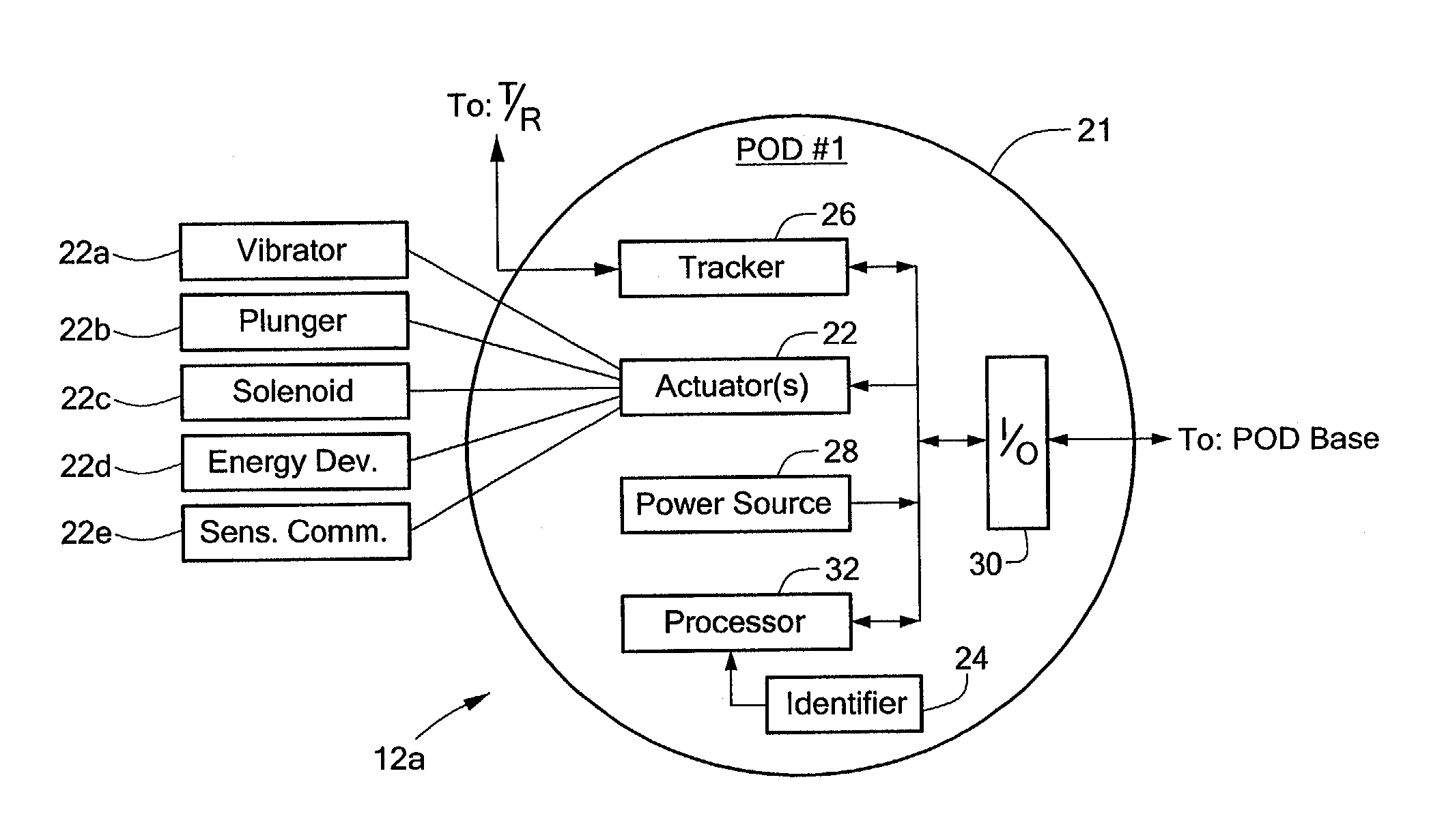
The present invention provides a distributed haptic interface system that can be easily reconfigured for different virtual reality applications. The system includes a reconfigurable haptic interface system with at least one sensory communicator or pod that can be mounted on a moveable object, such as a human test subject. The at least one actuator associated with the pod can include a vibrator, plunger, solenoid, shocker, or sensory communicator. The system also includes a plurality of transmitter / receiver units mounted in a spatial frame of reference and a host computer that processes the relative position information of the at least one pod to control actuation of the at least one actuator associated with the at least one pod. The at least one pod includes a unique identifier and a tracker module that communicates the relative position information to the plurality of transmitter / receiver units. The system also includes a pod base station that receives and translates the plurality of instructions from the host computer into control signals for the at least one pod. The method of operating the distributed haptic interface system includes mounting the at least one removeable pod on a first portion of a moveable object, communicating position information of the moveable object to the host computer, and generating an actuation control instruction based on the position information. The system can be easily reconfigured by simply removing and re-mounting the at least one removeable pod on a different portion of the moveable object.

Problems solved by technology

However, the availability of a number of specific human / computer haptic interface devices or systems is often inhibited by a number of technical and economic factors.

Method used


Image

  • Distributed haptic interface system and method
  • Distributed haptic interface system and method
  • Distributed haptic interface system and method

Examples


Embodiment Construction

[0020]Referring to FIG. 1, an exemplary embodiment of a distributed haptic interface system 10 includes a plurality of sensory communicators or pods, 12a, 12b, 12c (hereinafter collectively referred to as “pods 12”), which are removeably mounted on a plurality of portions of a compliant moveable object 14. The pods 12 can include a number of position and / or orientation sensors, which each include an actuator adapted to communicate sensory information to the moveable object, which will be described in detail herein. The movable object can be moved, for example, along the axes of a three-dimensional Cartesian coordinate system 60a. The system 10 further includes a plurality of transmitter / receiver units 16a, 16b, 16c (hereinafter collectively referred to as “transmitter / receiver units 16”), which are mounted in a fixed position and in a communication relationship with the pods 12. In one exemplary embodiment, the plurality of transmitter / receiver units 16 can include an IS-600 Mark 2 ...


PUM


Abstract

A reconfigurable haptic interface includes at least one pod adapted to be removeably mounted on one or more portions of a moveable object. The at least one pod includes at least one actuator adapted to communicate with the one or more portions of the moveable object. The system further includes a plurality of transmitter / receiver units, which are in a communication relationship with the at least one pod. The plurality of transmitter / receiver units detect and communicate relative position information of the at least one pod to a host computer. The host computer processes the relative position information of the at least one pod to control actuation of the at least one actuator located on the at least one pod.

Description

STATEMENT REGARDING FEDERALLY SPONSORED RESEARCH[0001]This invention was made with government support under Grant Number N00014-01-1-0197, awarded by the U.S. Navy. The government has certain rights in the invention.FIELD OF THE INVENTION[0002]The present invention relates generally to a distributed haptic interface system and method and, more specifically, to a distributed haptic interface system and method for reconfiguring the system for adaptation to a number of virtual reality applications.BACKGROUND[0003]Virtual reality systems provide users with the illusion that they are part of a “virtual” environment. A virtual reality system typically includes a computer processor, such as a personal computer or workstation, specialized virtual reality software, and virtual reality I / O devices such as head mounted displays, sensor gloves, three dimensional (“3D”) pointers, etc. These devices sense movement of a human body through a variety of sensors, and send signals to the computer proc...

Claims


Application Information

Patent Timeline
Patent Type & AuthorityPatents(United States)
IPC IPC(8): G06F17/00G09G5/08
CPCA63F13/06G06F3/014G06F3/011A63F2300/1012A63F2300/8029A63F2300/1025A63F13/20A63F13/212A63F13/28A63F13/23
InventorVON WIEGAND, THOMAS E.PFAUTZ, JONATHAN D.
OwnerTHE UNITED STATES OF AMERICA AS REPRESENTED BY THE SECRETARY OF THE NAVY