Method of controlling an optical disk drive by calculating a target frequency of a DPLL signal

a control circuit and target frequency technology, applied in the direction of digital signal error detection/correction, instruments, recording signal processing, etc., can solve the problem of limiting the read rate of the drive data, the data seek time limit, and the time and processing overhead required for performing the seek function becoming high enough to affect the overall seek time, etc. problem, to achieve the effect of reducing the overall seek tim

Inactive Publication Date: 2006-12-05
MEDIATEK INC
View PDF8 Cites 3 Cited by
  • Summary
  • Abstract
  • Description
  • Claims
  • Application Information

AI Technical Summary

Benefits of technology

[0015]It is an advantage of the present invention that the controller calculates a target frequency for the DPLL signal during the seek mode thus reducing overall seek time.
[0016]It is an advantage of the present invention that the controller calculates a target frequency for the DPLL signal when a rotation speed of the spindle of the optical disk drive changes.
[0017]These and other objectives of the present invention will no doubt become obvious to those of ordinary skill in the art after reading the following detailed description of the preferred embodiment that is illustrated in the various figures and drawings.

Problems solved by technology

Slow response of the phase-locked loop results in the time and processing overhead required for performing the seek function becoming high enough to affect overall seek time and performance of the CD or DVD drive.
In many cases, such as high-speed (32X–48X+) CD-ROM drives, a limiting factor in drive data read rate is data seek time.
This problem also exists in other types of CD and DVD drives to varying degrees, and typically, additional time and processing overhead is required to overcome it.
This type of optical drive control circuit is well known in the art and can suffer from slow response and long stabilization time.
Therefore, prior art optical disk drives, such as CD and DVD drives, have phase locked-loop control circuits and control methods that do not provide adequate seek times. Furthermore, the stabilization time of the prior art control circuit is too long during the seek mode or during a time when a spindle rotation speed of the optical disk drive changes.

Method used


Image

  • Method of controlling an optical disk drive by calculating a target frequency of a DPLL signal
  • Method of controlling an optical disk drive by calculating a target frequency of a DPLL signal
  • Method of controlling an optical disk drive by calculating a target frequency of a DPLL signal

Examples


Embodiment Construction

[0021]The present invention applies to optical disk drives such as compact disk (CD) drives and digital versatile disk (DVD) drives. Currently, there are a large number of applications of these drives such as CD-ROM, CD-RW, and DVD+RW to name just a few.

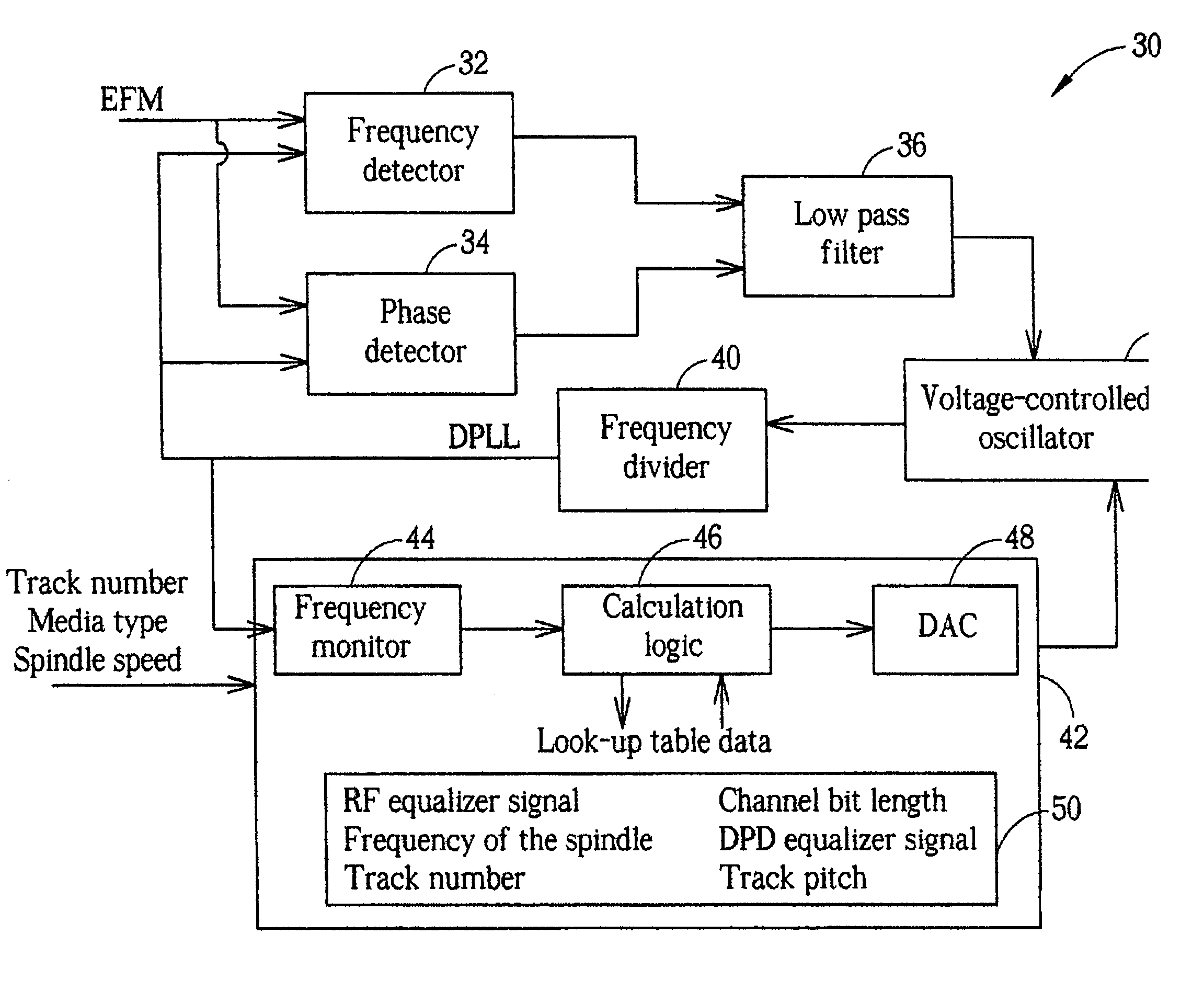
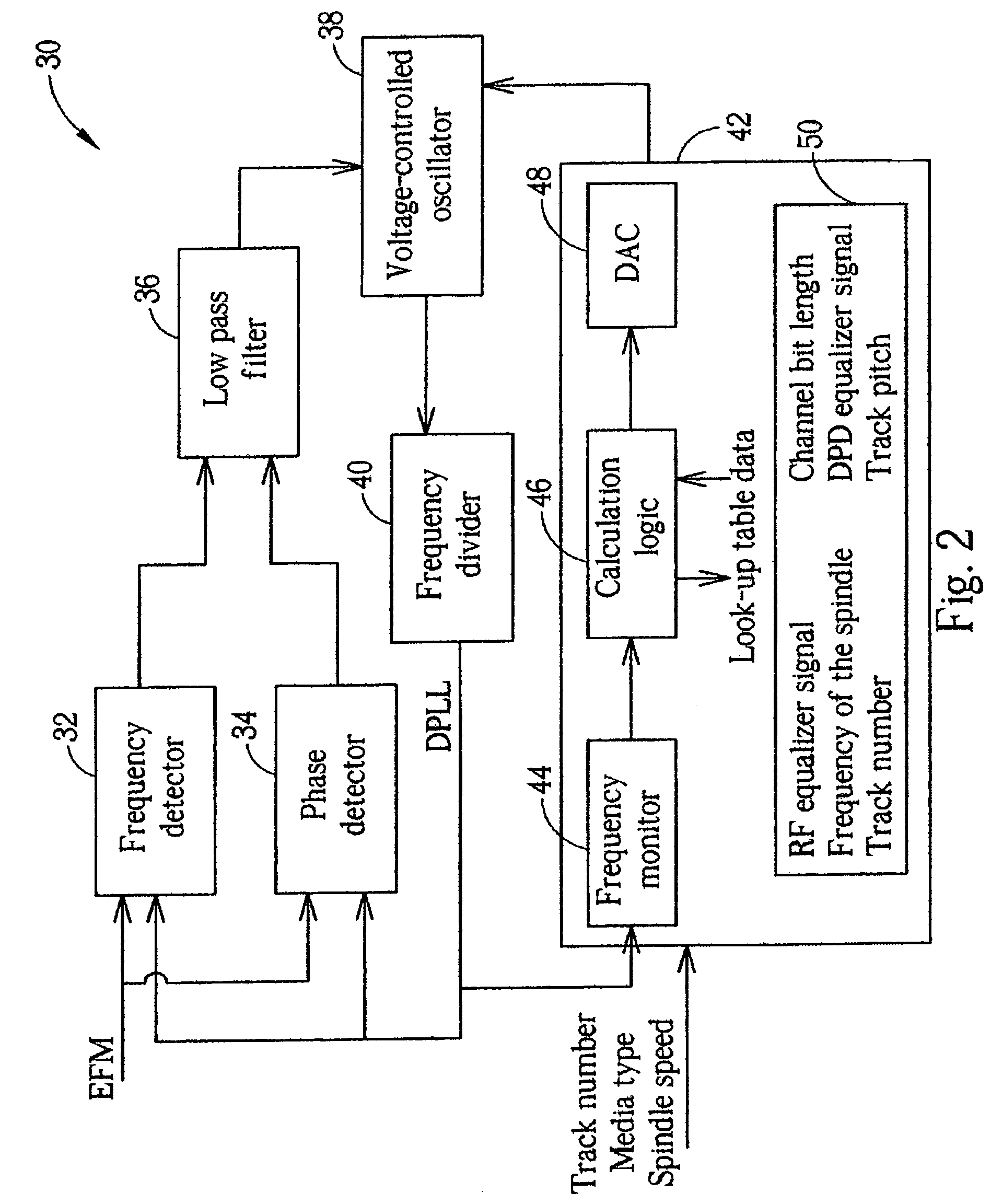
[0022]Please refer to FIG. 2. FIG. 2 shows a block diagram of a control circuit 30 according to a preferred embodiment of the present invention. The control circuit 30 includes a frequency detector 32 and a phase detector 34 having outputs connected to a low pass filter 36. An output of low pass filter 36 is connected to a voltage controlled oscillator (VCO) 38. The VCO 38 has an output connected to a frequency divider 40, which is connected to inputs of the frequency detector 32 and the phase detector 34. The VCO 38 is capable of receiving multiple signals and switching or otherwise selecting between these signals. The control circuit 30 further includes a controller 42 connected to the output of the frequency divider 40. An output ...


PUM

PropertyMeasurementUnit
pitch lengthaaaaaaaaaa
frequencyaaaaaaaaaa

Abstract

A control circuit for an optical disk drive includes a frequency detector, a phase detector, a low pass filter, a voltage-controlled oscillator (VCO), and a controller. The frequency detector and the phase detector both receive an eight-to-fourteen modulation (EFM) signal and a data phase-locked loop (DPLL) signal. The controller can calculate a target frequency and control the VCO to output the DPLL signal according to the target frequency. During a non-seek mode, the VCO outputs the DPLL signal according to output of the frequency detector, phase detector, and low pass filter. During a seek mode or when spindle speed of the optical disk drive changes, the VCO outputs the DPLL signal according to the target frequency. The controller further outputs charge pump currents for the frequency detector and the phase detector and sets an RF equalizer signal and a differential phase detector (DPD) equalizer signal according to the target frequency.

Description

BACKGROUND OF INVENTION[0001]1. Field of the Invention[0002]The present invention relates to an optical disk drive, and more specifically, to a control circuit and method for controlling an optical disk drive.[0003]2. Description of the Prior Art[0004]Optical disk drives such as compact disk (CD) drives and digital versatile disk (DVD) drives are widely used storage devices. Aside from audio and video information CDs and DVDs are commonly used to store computer software and other data.[0005]Essentially, both CD and DVD disks comprise a spiral track from which data can be read by an optical pickup head of the CD or DVD drive. During a read mode, the optical pickup head is controlled to follow the spiral groove to sequentially read data from the disk. During a seek mode, when a track or frame seek function is executed, drive electronics control the optical pickup head to move to a new frame or new track of the disk.[0006]According to the prior art, the drive electronics reference tabu...

Claims


Application Information

Patent Timeline
Patent Type & Authority Patents(United States)
IPC IPC(8): G11B7/00G11B7/085G11B19/247G11B20/10G11B20/14
CPCG11B19/247G11B20/10009G11B20/10425G11B20/1403G11B7/08505G11B2020/10916G11B2020/1461
Inventor HO, HSU-FENG
Owner MEDIATEK INC
Why Eureka
Try Eureka